 |
| Yum yum! |

Dale's Gardner Douglas 427 mk4 Building an AC Cobra re-creation
Sunday, January 31, 2016
Saturday, January 30, 2016
Cobra body on!
After spending an hour helping Keith Akerman fit his GD 427 body today with a load of friends from the Northern Cobra Club, Simon Smith suggested that they come down to my house and help fit my body (about 30 mins drive from Keith's). On arriving home it was snowing and very windy, not the best time to fit a sportscar body! But without their help I could not have got the body on - a great help, thanks to all of you.
Luckily, I had prepared the chassis and body, so that all the difficult jobs that I could do before the two parts (chassis and body) were married had been done.
Andy from GD had given me some tips and the first hand experience with Keith's helped a lot. First I had lightly rubbed down the mountings and filed the top edge off the middle mounting. Then I lubricated all the mountings with Vaseline. I removed the bonnet to make the body a bit lighter.
Andy had recommended that I have someone at each corner and someone to guide the process (me). In the end I had plenty of helpers. The body was rolled outside the garage and then the chassis was moved out then back into the centre of the garage.
Next the guys carried the body back into the garage over the chassis.
The trick was to get the body high enough over the chassis, then lower it down equally at either side.
 At the front the inner wings tend to be flexed slightly inward (hence my head in the radiator slot!), so this area needed help to get them over the chassis. Once the body was on the chassis, it had to be wiggled forwards towards the engine. The body needed to sit snuggly up against the transmission tunnel mountings where the tunnel flairs outwards, so that the front transmission tunnel bolts could be encouraged into place.
Andy had emphasised that the bolts should be greased and should go in easily. If I didn't take note of this the bolts could seize in the mounts or the bolt could twist the thread out of the rubber mount. This will be left until another day - now it is a case of stand back and admire!
 |
| A great crowd from the Northern Cobra Club helped me get the body on |
Andy from GD had given me some tips and the first hand experience with Keith's helped a lot. First I had lightly rubbed down the mountings and filed the top edge off the middle mounting. Then I lubricated all the mountings with Vaseline. I removed the bonnet to make the body a bit lighter.
Andy had recommended that I have someone at each corner and someone to guide the process (me). In the end I had plenty of helpers. The body was rolled outside the garage and then the chassis was moved out then back into the centre of the garage.
 |
| Body outside |
 |
| Chassis in centre of garage |
 |
| Body being carried into garage |

 |
| I have a car now! |
Thursday, January 28, 2016
Preparing to fit the body
Before I can put the body on, I needed to do a few small jobs. These will be easier now than when the body is on. Some must be done before the body can be fitted e.g. grinding down the mountings, cutting the recesss for the air intake, cutting out the hole for the gear lever etc, others can be done after, although it may not be as easy!
Had a chat with Andy at GD for any advice. Received some good tips.
Edit: Do fit the loom before you fit the body or at least connect the speed sensor, the reverse light switch and the starter motor. It is so much easier at this stage.
Now I just need to prepare for the day!
Mountings
I couldn't help taking a few photos of the chassis, before it gets covered with the body. This was one of the reasons that I went with Gardner Douglas. The engineering is miles ahead of the competition. No wonder people praise the handling of this car.
The rear mountings have been marked out in the boot to show the centres of the two mounting holes.Mine were 532 mm from the centre of the car to the centre of each mounting. The holes will be about 20 mm up from the floor of the boot apparently.
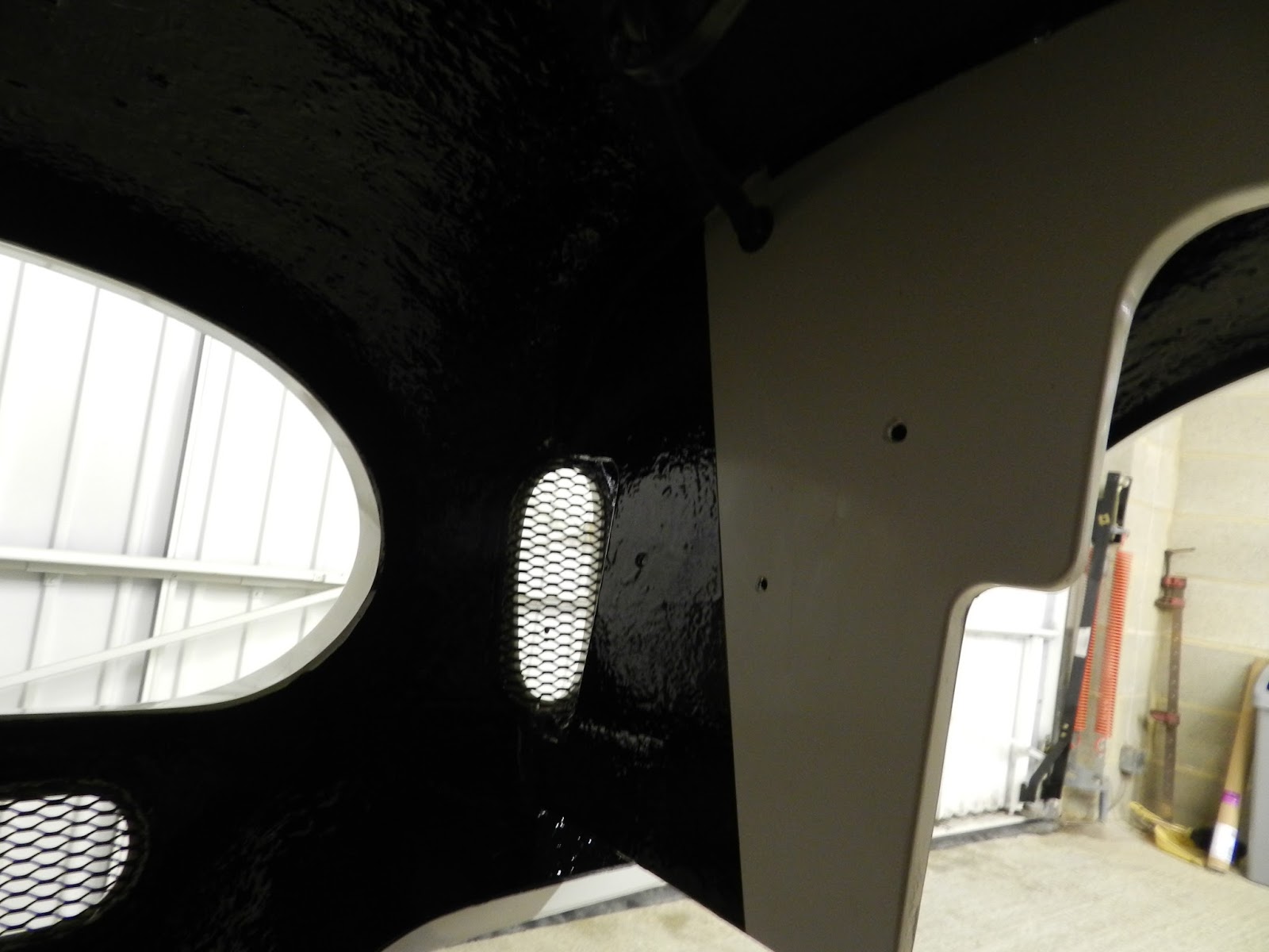
Air intake cut out
The lip and hinge mounting point needs to be shaped to allow the air intake to fit up into it. The area to remove was marked up centrally on the body. The Dremel with a sanding tube came in handy here to grind out the GRP. The air intake was offered up regularly to check the cut out.
Under sealing area ahead of radiator
The inner wings were not undersealed when the wheel arches and nose were done. At that stage I didn't know where the lines should go. I used the mounting holes on the inner wings to determine where to put the masking tape, prior to applying the underseal.
Gearbox oil
Yes, this is automatic gearbox oil, even though it is a manual! Tremec recommend AQT oil. It is easier to fill the gearbox now than when the body is on.
Gear lever hole
This needs cutting out in the transmission tunnel, prior to mounting the body. I used the mounting holes as reference points to locate the centre of the gear lever hole. This is towards the nearside, but once the gator and escutcheon is fitted it will look central. Once marked this was cut out using a hole cutter.
Footwell extension
The footwell extension was rubbed down, after I had applied some more gel coat to help get a better finish. The fixing screws will need shortening to tidy it up a little.
Horn
The horn wire is on the nearside at the front. Fitting was a case of drilling three holes (the compressor and two trumpets) in the chassis and fitting rivnuts. The brackets were fitted to the rivnuts using button head screws and then the compressor and trumpets were fitted to these brackets.
Boot carpet
Now that the reverse and fog lights were fitted, I could fit the piece of carpet at the back of the boot. This went under the striker plate, which was bolted through the floor, before the carpet was glued down (not glued yet). The striker plate does not go down to the floor, so once the carpet was in place I made up some spacers out of the spare aluminium bar that I had used for the radiator.
Odds and ends
The reversing light wire on the offside of the gearbox and the loom need connectors attaching. The existing connection on the gearbox was removed first.
The speedo connection from the loom will need a Delphi two pin waterproof connection adding - I hate making up those things. I will need to order this.
The rubber bung below the reverse lockout on the nearside was cut down and then a plate made to secure it in place.
Surplus vacuum take offs were blocked off with button head bolts and Araldite adhesive.
Preparing for body fitting
I have been told to remove the radiator frame and, after slackening the lower bolts, tilt the radiator back a little. This will stop the body fouling on the chassis at the front. A bungy helped to hold all this in place.
Had a chat with Andy at GD for any advice. Received some good tips.
Edit: Do fit the loom before you fit the body or at least connect the speed sensor, the reverse light switch and the starter motor. It is so much easier at this stage.
Now I just need to prepare for the day!
Mountings
I couldn't help taking a few photos of the chassis, before it gets covered with the body. This was one of the reasons that I went with Gardner Douglas. The engineering is miles ahead of the competition. No wonder people praise the handling of this car.
 |
| Rear three quarter view of chassis |
 |
| Front three quarters view of chassis |
The rubberised body mountings, where the transmission tunnel splays out, need the top edge grinding to an angle to help the body sit on the chassis. Also I have checked that the mountings are sitting flush with the chassis. The mountings will be lubricated with Vaseline to help jiggle the body in to place.
 |
| Top mounting filed down. Note that this mounting does not have a screw thread |
The mountings were lightly sanded to take off any sharp edges.
 |
| Lightly sanded mounting |
Air intake cut out
The lip and hinge mounting point needs to be shaped to allow the air intake to fit up into it. The area to remove was marked up centrally on the body. The Dremel with a sanding tube came in handy here to grind out the GRP. The air intake was offered up regularly to check the cut out.
 |
| Cut out at front of body |
The inner wings were not undersealed when the wheel arches and nose were done. At that stage I didn't know where the lines should go. I used the mounting holes on the inner wings to determine where to put the masking tape, prior to applying the underseal.
 |
| Final bit of underseal! |
Yes, this is automatic gearbox oil, even though it is a manual! Tremec recommend AQT oil. It is easier to fill the gearbox now than when the body is on.
 |
| Filling the gearbox with AQT |
This needs cutting out in the transmission tunnel, prior to mounting the body. I used the mounting holes as reference points to locate the centre of the gear lever hole. This is towards the nearside, but once the gator and escutcheon is fitted it will look central. Once marked this was cut out using a hole cutter.
 |
| Gear lever hole in transmission tunnel |
The footwell extension was rubbed down, after I had applied some more gel coat to help get a better finish. The fixing screws will need shortening to tidy it up a little.
Horn
The horn wire is on the nearside at the front. Fitting was a case of drilling three holes (the compressor and two trumpets) in the chassis and fitting rivnuts. The brackets were fitted to the rivnuts using button head screws and then the compressor and trumpets were fitted to these brackets.
 |
| Horn fitted to chassis rail |
Now that the reverse and fog lights were fitted, I could fit the piece of carpet at the back of the boot. This went under the striker plate, which was bolted through the floor, before the carpet was glued down (not glued yet). The striker plate does not go down to the floor, so once the carpet was in place I made up some spacers out of the spare aluminium bar that I had used for the radiator.
 |
| Piece of boot carpet at rear fitted - wrong way round! |
 |
| Piece of boot carpet fitted - right way round. |
The reversing light wire on the offside of the gearbox and the loom need connectors attaching. The existing connection on the gearbox was removed first.
 |
| Connections on gearbox for reverse light |
The rubber bung below the reverse lockout on the nearside was cut down and then a plate made to secure it in place.
 |
| Plate securing bung on gearbox |
 |
| One of the surplus vacuum take-offs blocked |
I have been told to remove the radiator frame and, after slackening the lower bolts, tilt the radiator back a little. This will stop the body fouling on the chassis at the front. A bungy helped to hold all this in place.
 |
| Radiator frame removed |
Tuesday, January 26, 2016
Fog and reversing lights
Initially I had taken the rear oblong lights, but on reflection I preferred the round lights on stand offs, so GD exchanged them.
There needs to be one of each as a minimum. The fog light needs to be red, whilst the reversing light needs to be white - nothing surprising here then. The rear fog light needs to have a tell tale light on the dash and a dedicated switch. The fog and reversing light need to be on the centreline of the body or off set, but the fog light needs to be more than 100 mm from the stop light!
The lights are mounted on shiny GD stand-offs. The positions were marked out on the body using masking tape - minimum height is 250 mm from the ground, maximum for the fog is 1000 mm and 1200 for the reversing light. The IVA is quite specific (this is the IVA as at Dec 2015). However, as my car body is not yet on the chassis, I looked at other blogs for the position. I reckoned that mounting them 15 mm down from the boot opening would be okay.
A 26 mm hole was drilled at each side for the cables and a grommet inserted. Smaller 5 mm holes were drilled at each side of the main holes for fixing.
The screws were not horizontal like the brake and indicator, so holes were drilled at 90 deg to the standard in the light fitting to correct this. The lights were then fitted, sandwiching the stand-offs (note that these are handed) between the body and the lights. Longer screws (45 mm) than supplied were needed for the lights.
There needs to be one of each as a minimum. The fog light needs to be red, whilst the reversing light needs to be white - nothing surprising here then. The rear fog light needs to have a tell tale light on the dash and a dedicated switch. The fog and reversing light need to be on the centreline of the body or off set, but the fog light needs to be more than 100 mm from the stop light!
The lights are mounted on shiny GD stand-offs. The positions were marked out on the body using masking tape - minimum height is 250 mm from the ground, maximum for the fog is 1000 mm and 1200 for the reversing light. The IVA is quite specific (this is the IVA as at Dec 2015). However, as my car body is not yet on the chassis, I looked at other blogs for the position. I reckoned that mounting them 15 mm down from the boot opening would be okay.
 |
| Lights marked out on masking tape |
 |
| Holes drilled |
 |
| Grommet fitted |
 |
| Reverse and fog lights fitted |
Sunday, January 24, 2016
Chevy LS6 heater hoses and vacuum tubes part 2
Here are pictures of the heater hoses fitted. I bought the heater hoses from SFS Performance and the stainless steel heater pipes from GD.
 |
| Offside hoses to heater |
 |
| Nearside hoses to heater |
 |
| Front view |
The hose to the header tank and the overflow, were fixed in place.
 |
| Header tank hoses |

Friday, January 22, 2016
Chevy engine loom and sensor connections
LS6 engine connections from Canems engine loom
Here is my take on the wiring for an LS6, but if you use this please do check it yourself as the engines do differ depending upon age. Yes it is a bit complex and boring, but is essential in getting the beast going! Apologies if this is obvious to you - it wasn't to me.
This might seem premature, as the wiring loom will not be installed until the body is put on the chassis - a few weeks away yet!
The first part of the notes below gives the loom connection tag on the Canems loom. The next bit is the number of wires. The final bit is where it goes on the engine. As I struggled, there are also some pictures of the sensors to help identify them.
Engine
The first part of the notes below gives the loom connection tag on the Canems loom. The next bit is the number of wires. The final bit is where it goes on the engine. As I struggled, there are also some pictures of the sensors to help identify them.
Engine
- Air temperature sensor (IAT) - 2 wire connector- fitted into air intake sensor on air intake tube

Air intake sensor - Alternator - 4 wire connector – alternator on nearside of car
- Alternator - 2 joined red wires with ring - alternator back, fixing post secured with nut

Small amount ground out of block to accommodate alternator

Alternator fitted, using GD spacers - Coolant temperature sensor - two wire - sensor in nearside head at top of manifold next to port 1.

Coolant sensor - Cam sensor - 3 wire connector - at front of engine near water pump, below throttle. There is also a cam sensor at the back of the engine (between the plenum and engine block) which is not used.

Cam sensor at front

Cam sensor at rear (not used) - Injector
1 - 2 wire connector - nearside injector 1 (front)

Injector connector


- Injector 3 - 2 wire connector - nearside injector 2
- Injector 5 - 2 wire connector - nearside injector 3
- Injector 7 - 2 wire connector - nearside injector 4 (back)
- Odd coil - 7 wire connector - on top of rocker cover nearside

Coil connector - Earth connection - 1 wire ring - to chassis
- Not marked on mine - round connector 1 - to GD Body Loom (different size to other)
- Not marked on mine - round connector 2 - to GD Body Loom (different size to other)
- Oil pressure switch - 1 wire 6.3 mm spade - oil pressure sensor to be installed Edit - location at rear of block currently blanked off

Where oil pressure sensor fits - Reverse light - 2 wire - to gearbox connector - front connector on gearbox with wire
- Odd lambda - 4 wire connector - nearside lambda in lower bend of manifold
- Odd knock - (mine was in the valley between the two heads) single green wire - discard the connector on the engine and do not use the black earth leads. Connect nearside knock lead of loom to rear sensor

Knock sensors in centre
To get at the knock sensors to check their position and wires, required the removal of the fuel rails and the injectors (4 bolts) and the plastic plenum along with the throttle body (10 bolts)


- Oil
temperature sender - 1 wire 6.3 mm spade - to sensor above oil filter on nearside

Oil temperature - Throttle
position - 6 wire connector – nearside of throttle (throttle pot)

Throttle position sensor - Throttle – 2 wire connector – offside of throttle

Throttle two wire black connector (on offside) - MAP (manifold absolute pressure) sensor - 3 wire connector at the back of the engine fitted into the plenum

MAP sensor - Injector 2 - 2 wire connector - offside injector 1 (front)
- Injector 4 - 2 wire connector - offside injector 2
- Injector 6 - 2 wire connector - offside injector 3
- Injector 8 - 2 wire connector - offside injector 4 (back)
- Even coil connector - 7 wire connector on top of rocker cover offside
- Crank sensor - 3 wire connector - 90 deg connection above and behind the starter motor on the offside

Crank sensor tucked behind the starter - Water temperature sensor - 6.3 mm spade connector - to a new sensor Edit - on offside head near bulkhead above plug/cylinder 8

- Starter solenoid - 2 red connected wires with ring - to lower terminal (without connection to starter)
- Starter solenoid - slate/red wire with ring - to green covered terminal
- Even
lambda – 4 wire connector – offside lambda in lower bend of manifold

Offside lambda sensor - Even knock - (mine was in the valley between the two heads) single blue wire - discard connector and do not use the black earth leads. Connect offside knock lead of loom to front sensor
- Pedal – 6 wires connector – to electronic pedal connector

Electronic pedal with connector on right - 6.3 mm spade – 1 wire near relay – to terminal 87 on that relay (if not already looped)
- Battery 12v ring connection - 1 thick red wire - 12v supply from battery
- "Pump" lead - 1 wire pink/white - connect to pump wire in body loom


Gearbox
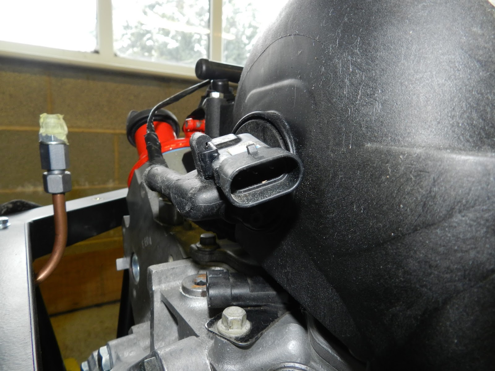
- The speedo pick up is near the tail of the gearbox on the offside

Speed sensor - Two wires go to the front connection on the offside (nearest the bell housing) for the reverse lights

 |
Reverse light (in US terminology back up light) connector
|
- The reverse lock out, which I do not plan to connect initially (will just run a pair of wires to the dash area), is at the rear of the gearbox on the nearside.


Drive belt
The belt was fitted. The idler pulley was removed (see earlier post - Small but important jobs). It simply went around the water pump, the alternator, the crank pulley and the tensioner. The tensioner was levered with a long screw driver to get the belt on!
 |
| Belt path can be seen here |
Subscribe to:
Posts (Atom)