Monday, March 28, 2016

Dashboard - part 4

With the leather and piping in place, I thought that I should check that the screws were still aligned with the holes in the scuttle. They weren't, so I had to elongate the scuttle holes a little to allow the dash panel screws to fit into the holes.

The holes were cut for the gauges. The leather was cut from the back with 16 scores to create a load of tabs that would push through with the gauges and be stuck down at a later time.
Leather cut ready to take gauges
The gauges were relatively easy, but the switches and warning lights were less so. I ground down a small craft type knife to allow access to the smaller holes and then cut the leather for these.

Gauges pushed through. Leather tabs still to be glued down
All the switches, warning lights and gauges were fitted in place.
The finished dashboard
The warning lights were inclined to move, so I applied some silicone around these at the rear. Now it has been put aside to cure. The tabs were glued using contact adhesive and then trimmed.

The dash loom was marked up using the wiring diagram, in preparation for the wiring job.

Dashboard - part 3

Today was gluing the leather. Don't rush it I told myself.

The dash leather was pre-cut to shape about 25mm extra all round. First I glued the bottom in place - about 30mm wrapped around the bottom, but not on to the back. Next I glued the top in place, gently pulling the leather tight.
Lower lip glued, but top edge still to do
Top edge gently pulled over and glued
Then I spent ages trimming the ends, around the tight radius. No tips here, just have patience. I then stuck the piping in place. This was a case of applying the  adhesive onto the piping edging and on to the back (about 10mm) and top of the dash. The piping was then carefully fixed after the glue had gone tacky.
Piping glued to blank dash
Top piping
Next I cut out the hole for the steering column, leaving sufficient leather to stick to the lip. The top of this hole is curved, so I made a number of V nicks in the leather, before applying the adhesive. Then I stuck on the piping to finish it off.
Hole for steering column piped

Saturday, March 26, 2016

Dashboard - part 2

So now it was down to cutting the big holes (102mm) for the speedo and rev counter. To cut these I used the Dremel hole cutter. Both holes were cut out slightly undersized, then opened out to the correct size with a half round file. The backs of all the holes were slightly raggy with strands of fibre glass. A flapper wheel sander in the drill soon sorted this out.
Holes cut in dash panel
The instrument holes in the dash panel were used to mark where the instruments would overlap the scuttle lip at the top. This was trimmed with the Dremel, so that no gauge would touch the scuttle lip. In my case only the two large gauges needed to be catered for. The panel was rubbed down with wet n dry to provide a key for the adhesive.

Next I fixed the four countersunk screws into the holes previously drilled in the dash panel, using Araldite adhesive.

Now I needed to glue the foam to the dash panel. Spray contact adhesive was applied to both surfaces and after leaving for a few minutes the dash panel was laid over the foam and pressed firmly into place. The netting side of the foam was stuck to the dash panel. The foam was fixed to the underside of the dash panel, but not wrapped right around to the back. The foam was cut with scissors, leaving a 10mm overlap around the curved part of the panel. This was glued and wrapped around the edge of the panel and glued to the back of the panel. Finally the holes were cut out of the foam using a craft knife. This sounds easier than it was. Not perfect holes (but nearly). These will have the instruments fitted in them and be covered by the leather, so any hole imperfections won't show.
Back of dash panel - foam glued, but holes not yet cut.
Captive screws can be seen, as can the thinned areas for the switches
Front of dash panel - holes now cut and awaiting leather trim
Now the panel has been left to cure/dry, before the leather is applied.

Friday, March 25, 2016

Dashboard - part 1

Now I have all the gauges, switches and warning lights, I thought that I should get on with it. The day was sunny and relatively warm, so I could work outside. Keeps the dust off the Cobra!

First I fettled the ends of the dash GRP panel. These were fouling the hinges at each side, so needed trimming with the Dremel. Four 5mm holes were then drilled in the GRP panel, two across the top and two at the ends near the doors (see the photo below). These were countersunk to take the screws, which at the moment were left loose. Four 6mm holes were drilled in the scuttle lip to take the dashboard screws. This allows for any slight misallignment of the dashboard screws.

I was not happy with the position of the switches and related warning lights that I had come up with, so these were repositioned. The dash was trial fitted to ensure that I could see the switches and warning lights from the drivers seat with the steering wheel in place. Once I was happy, the gauges, switches and warning light hole centres were marked on masking tape and re-measured and measured again to make sure that they were in the correct place.
Hole centres and diameters marked
The hole diameter was marked on the masking tape to remind me what sized hole to drill, allowing 1mm either side for the leather. So each hole was 2mm bigger than the actual size of hole needed. A step drill was used to avoid any chipping of the GRP. Where I did not have the right sized hole cutter, I made the hole undersized and then opened it out with a file or the Dremel, checking the hole size with digital calipers as I went. When I had drilled each hole I checked that the instrument fitted ok. I had made the hazard switch hole too small, as I had measured the thread size, forgetting that the switch body went into the hole. At least it was the right way - too small a hole.

The switches do not have a very long threaded section around the switch lever, so the GRP needed to be thinned at the back of the panel a little to allow them to come through sufficiently.

Tuesday, March 22, 2016

Engine sensors fitted

So the instruments have arrived. Now I needed to fit the engine sensors.

First was the oil pressure sensor. Not straight forward! I had to loosen the plenum first so that the sensor would fit. Without this being removed the sensor was too wide at the base. The sensor is fitted in to the M16 to 1/8" NPT adapter. I had to tighten the adapter to the sensor first, before I used grips to gently tighten the sensor in the hole. The wire to the loom was then attached.
Oil pressure sensor in place. Spare terminal is for an oil warning light.
Next came the water temperature sensor. This is fitted to the back of the off side head and there is little space! The back spark plug connection was removed to give a little more space. The adapter was again fitted to the sensor, before tightening in the head. Finally the loom wire was attached.
Water temperature sensor fitted
Finally the oil temperature sensor was fitted. For a change this was easy. Accessing the oil filter housing from under the car, the adapter - pre-fitted to the sensor, was screwed in place then tightened and the loom wire attached. NOTE: Do make sure that the sensors are tightened - I hadn't!
Oil temperature sensor fitted
Now, whilst in the engine compartment I did a couple of small jobs. First, I am embarrassed to say, was to swap the rocker covers around. I had re-fitted them on the wrong sides. D'oh! Not that it matters that much, but I had decided that it would be easier to fill with oil if the filler was on the off-side. This required the coils and plug lead assembly to be removed from the covers and re-fitted to the correct cover. The fitting of the vacuum pipe had to be modified slightly too.
Rocker covers right way round. Note filler on left of photo.
Next came the washer bottle connection. The water tube was fed through the lower hole in the bulkhead (after fitting a grommet) and connected to the outlet on the washer pump. The two wires were also fed through the hole and connected to the pump.
Water tube and wiring
Just to fill in the time I set up the dash with the steering wheel to check if I could see all the warning lights and gauges - I couldn't, so have moved a few things round. So here is how it looks at present. The GRP panel will need some fettling to avoid the hinges binding and to closely follow the scuttle contour, whilst allowing for the leather trim.
Revised dash layout after loosely fitting the wheel

Monday, March 21, 2016

Gauges and sensors arrived

Great service from ETB - delivered as promised. I even had to delay the delivery myself, with being away!

So here they are clockwise - M12 to 1/8th NPT adapter, oil temperature sensor, M16 to 1/8th NPT adapter, oil pressure sensor, oil pressure gauge, oil temperature gauge, programmable speedo (150 mph), fuel level gauge, tachometer (8000 rpm), water temperature gauge, volt meter, water temperature sensor, M12 to 1/8th NPT adapter and in the centre (the long thing) the dip tube fuel level sensor.
Gauges and sensors

Sunday, March 13, 2016

Roll over hoops - part 2

The hole at the other side of the car (nearside) was drilled, like the first and opened out..
Two holes drilled
A straight line was marked across the boot of the car, using a straight edge. Bolts in the two holes were used to position of the line.  The hole centres were marked 304mm (12 inch) apart, from each inner hole centre. The loom needed to be unclipped on the nearside and the carpets pulled back. A small screw driver helped check that the holes were lined up with the mounting points. Once I was sure that the hole centres lined up, they were opened out to 55mm (the bars are 51mm) to allow the roll over bar legs to go through.
Two bolts used to check the hole centres
So all four big holes drilled in the boot floor. May need to open them up a little more, but that is for another day if required!
Four holes drilled, centred and opened out
So, steady progress. The two holes for the third legs will have to wait.


Thursday, March 10, 2016

Roll over hoops - part 1

Seats

Couldn't resist putting the seats in the car to see what they looked like!
Really happy with the look!
Had to cut the carpet out from around the handbrake bracket, then bend the bracket a little to gain clearance with the drivers seat.

Setting up the car

Next I levelled the car on axle stands. The chassis is the thing that is set to the level, not the body. It needs to be level side to side and back to front. This took hours!

Front wheels

Whilst it was up on the axle stands, I checked whether the front wheels, when on full lock, touched the inner wings. They did! So using the Dremel, I dressed the lip on the inner wing back a little to create some clearance. This was required at the front and back of the front wheels.
Small area removed from inner wing to allow tyre clearance
Roll over hoops

Now to the butt nipping bit! I have been putting this one off, but the time has come when I can't do this any longer.

The items involved in fixing the roll over bars are the two stainless steel hoops, the saddles/brackets and the fixings. These differ from the GDJAG to the Euro, in that the fixing points have different spacing. So unlike me, do not assume that a template from a JAG will fit. It won't. You will need to make your own template if you can't blag one (not that I really needed one)!
Roll over bars, saddles and bolts
The saddles/brackets are made of steel and needed to be painted before fitting. I used Hammerite satin black spray.

Levelling up the chassis was important as it will allow the plumb bob to line up with the mounting vertically. The rear half of the chassis was the most important as this is where the bars are mounted. Finding flat areas of the chassis to check the level, however, was a challenge!

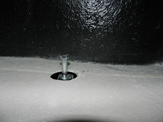
Now to some real work. A 5mm hole was drilled up through the inner front mounting point of the chassis into the boot floor. I used a 90 degree chuck adapter for the drill and plenty of dexterity to get the drill in place around the suspension! Why has no one invented a bendy drill? Next I made an undersized hole (about 40mm) with a hole saw. Finally I marked a circle using the mounting hole as a centre point and opened it up with the Dremel. I then made sure that the mounting point was in the centre of the new large hole. It was, phew!
Hole with chassis mounting point below
First hole in [place with bolt designating the centre of the hole
The other holes will wait until I am fresh to the job. So now for some wine and a feet up!

Wednesday, March 09, 2016

Seats and leather trim arrived

The seats, headrests, door cards, gear lever gaitor, handbrake gaitor, dash padding and dash leather have arrived from Intatrim.
The seats and leather trim (less the dashboard)
They are Muirhead leather in black (DA099), with red stitching to match the carpets.
Red stitching detail can be seen above

Sunday, March 06, 2016

Battery and fuel lines

Battery

The battery installation is fairly straight forward. There are three major components - the battery tray (which is stainless steel), the battery itself and the restraining bracket (which is a triangular fabrication in stainless steel), plus a few nuts and bolts to hold them in place.
The parts
The battery tray was installed in the nearside compartment and fixed to the floor. Some thin rubber strip was fitted in the tray to physically isolate the battery from the tray.
The tray in place without the rubber strip
The compartment opening had to be cut out a couple of millimeters each side to allow the battery to be put in to the compartment and tray.

The restraining bracket was bolted to the bulkhead (in front of the passenger footwell) above the centre of the battery to secure it in place. To do this I marked and drilled two holes through the bulkhead. Each bolt was passed from the passenger compartment, through a penny washer and into the compartment behind the front wheel arch. The bolts were inserted into an alli bar that had been tapped to take the bolts. The tapped holes in the bar had thread lock applied.

Again some rubber was fitted to the underside of the bracket (where it would touch the battery) to isolate it. Finally the bracket was fitted onto the two screw shanks and held in place with nuts.

The cables could now be connected. Mine wasn't, as other electrical work had not been completed, so I only connected the earth leads at this stage.
Battery and bracket installed
Fuel lines

There are two fuel hoses and the electrical connection to get from the pump into the boot.

Three holes were drilled in the boot upstand (the section that the tank goes against). These were drilled at the nearside, near the wheel arch, the top and bottom holes were level with the two unions on the tank. The top hose was a tad short, so the hole had to be re-drilled closer to the tank so that it would connect. The third hole, for the wires, was drilled in the middle of the other holes.
Holes marked
Each hole had the GRP thinned to allow a grommet to be fitted. The grommets were eased over the hoses and wires. A little Vaseline here helped! The 90 degree ends of the two fuel hoses had been removed before the grommets were fitted.

Now the hoses were threaded through to the boot from the axle area. The wires were fed through from the boot side to the axle area and the grommets secured in place. The wires were then connected to the pump. The grommets were siliconed in place and the unions re-fitted to the hoses.
Hoses and electrical cable from boot
Hoses and electrical cable from underside
The fuel tank installation will wait until another day.

Friday, March 04, 2016

Gauges, sensors and switches

I have decided not to replica an old Cobra dashboard look or the standard GD layout. For example, I do not want the counterclockwise speedo and the usual GD pyramid style layout of gauges is not to my liking. So I have gone for a mix of Lucas type switches, modern billet alloy switches, warning lights with silver bezels and gauges that are a mix of traditional and more modern. Sounds dreadful when you write it down!

Switches and warning lights

What I have bought is:

Push button start - momentary
Push button hazard - latching
Flick switch for fog light - on/off
Flick switch for heater - on/on/off
Flick switch for lights - on/on/off

Indicator light warning - left
Indicator light warning - right
Brake warning
Battery warning
Fog light warning
Main beam warning

Gauges

What I do want is to have kph shown alongside mph on the dial, in case I drive abroad. I also want black background gauges, with red pointers and IVA compliant bezels. Originally I was going to go with white backgrounds, but Carol (my wife) thought that they didn't look as good as black ones.
The ETB speedo with mph and kph
I have decided on ETB gauges, as they can be configured as I want, are a good price and delivery timescales are relatively short.

I will have the following gauges a speedo, rev counter, oil temperature, oil pressure, water temperature, voltmeter and a fuel gauge.

Sensors

I need some specific sensors and adaptors, so I had to identify where these went and the thread sizes before I could place the order! John Gare at ETB was a great help here (see link on right), as was Dave Hampshire at Canems. LS1tech.com is usually very good at helping sort out these things, but this time the posts were just confusing - everyone seemed to have a different view of where the sensors were located and what the thread size was.

What I eventually concluded for my LS6, was that two adaptors were required for the temperature sensors (water and oil). These are  M12 x 1.5 threads to take 1/8" NPT sensors, one located at the rear of the offside head (water) and the other above the oil filter on the nearside. This tied up with what John Gare at ETB had said. The existing water temperature sensor is still used as well.
Existing water temperature sensor
New water temperature sensor position at rear offside
Old oil temperature sensor
My next challenge was to work out where the oil pressure sensor went. This turned out to be at the back of the engine on the nearside and the near the valley (it was blocked off with a big grub type screw) and needs a M16 x 1.5 threaded adaptor, to take a 1/8" NPT sensor. Again the size of the thread tied up with what John at ETB had said.
Where the oil pressure sensor will go
The fuel sensor will be a dip tube (this will match the gauge electrically), rather than the float arm type. This is a VDO product and works by having a float that moves up and down inside the dip tube. This is apparently more accurate, but a little more expensive. The dip tube needs to be the depth of the tank, less about 4 mm and also allow for the reserve fuel! So I decided on a 260mm dip tube after a lot of calculating.
Fuel sensor dip tubes 
Order placed

So I have ordered the following gauges:
  • Speedometer
  • Tachometer (rev counter)
  • Fuel gauge (compatible with a dip tube)
  • Oil temperature
  • Oil pressure
  • Water temperature
  • Voltmeter
And the following sensors with adapters:
  • Oil temperature
  • Oil pressure
  • Water temperature (additional) 
  • Fuel sensor (dip tube) 260mm long