Registration
I had sent the forms off to the DVLA and they arrived on the 25 February thinking that all were there. I had not supplied a V627 form, because it did not look relevant to my car (seemed to be relevant to cars that had donor parts and not a brand new car) and the website was unclear to me.
The DVLA chased this up. I sent the response the same day to the DVLA on the 11 March (caught the post that day).
I chased up my application with the DVLA this morning (16th March). No progress or sign that they had received my response, despite being sent 6 days ago!
Had a call from Karen (case owner) at the DVLA this afternoon to say that all was ok and that the application had been approved. She had seen the record of my chase up telephone call. My personalised registration will also need assigning, so paperwork should be with me next week sometime.
Nearly there!
I told you that there is a difference between getting the car ready for the road and finishing it!
Ignition barrel
The grey central part of the ignition barrel had been sticking. It stayed in when the key was removed, when it should have sprung out. So a new one was bought via eBay. I got the barrel and two keys for only £12.30. This was cheaper than a single key at many places, so consider that before you buy another key. Also this is one of the very few pre-used parts.
Fitting is covered elsewhere on this blog, so I won't repeat it.
Outstanding work
Two outstanding jobs that I am aware of at this stage are to make the indicators self-cancelling and to put on some better side vents. Otherwise done!

Dale's Gardner Douglas 427 mk4 Building an AC Cobra re-creation
Showing posts with label Electrical. Show all posts
Showing posts with label Electrical. Show all posts
Thursday, March 16, 2017

Friday, January 27, 2017
Final checks
Electric test
I was happy that all the electrics were working now, but a check prior to the IVA would not go astray. The electrics were tested with the engine off (ignition on) and with the engine running. So here is my checklist:
The ride height was adjusted so that the bottom of the front indicators were a minimum of 350 mm from the floor. The adjustment was made by turning the spring collar clockwise on the shock absorbers. A 'C' spanner was used for this. Mine took 10 turns to get the ride height correct. To keep count of complete turns put a small piece of masking tape on the platform and one on the moving collar, then mark a line across both pieces (see photo below). My chassis was a Euro, so the ride height was initially set by GD.
Pre IVA
Here is a pre-IVA check list for the GD 427. The results are shown in italics. Some final tweaks will be done by GD prior to the test.
I was happy that all the electrics were working now, but a check prior to the IVA would not go astray. The electrics were tested with the engine off (ignition on) and with the engine running. So here is my checklist:
- Side lights - ok
- Dip lights - ok
- Main beam - ok
- Main beam warning light - ok
- Flash lights - ok
- Gauge back lights when lights on - ok
- Fog light - only when on dip or main beam - ok
- Fog warning light (only works on main lights, not side lights) - ok
- Heater speed 1 - ok
- Heater speed 2 - ok
- Reversing light - ok
- Indicator off side - front, side, rear and warning light - ok
- Indicator near side - front, side, rear and warning light - ok
- Hazard lights - all indicator lights flash - ok
- Hazard warning - mine does switch, left and right indicator warning lights - ok
- Horn - ok (loud)
- Ignition light - goes out when engine running - ok
- Wiper - intermittent (if fitted) - ok
- Wiper - speed 1 - ok
- Wiper - speed 2 - ok
- Washer - ok
- Brake fluid warning - from drivers seat (via ignition) and push on top of reservoir - ok
- Brake lights - ok
The ride height was adjusted so that the bottom of the front indicators were a minimum of 350 mm from the floor. The adjustment was made by turning the spring collar clockwise on the shock absorbers. A 'C' spanner was used for this. Mine took 10 turns to get the ride height correct. To keep count of complete turns put a small piece of masking tape on the platform and one on the moving collar, then mark a line across both pieces (see photo below). My chassis was a Euro, so the ride height was initially set by GD.
 |
| Markers on all four shockers |
Here is a pre-IVA check list for the GD 427. The results are shown in italics. Some final tweaks will be done by GD prior to the test.
- Fit IVA fog light - needs to work only when main lights on (not side lights) - GD
- Check number plate light bolt radius - Done
- Change boot handle for IVA compliant (radiused) version - GD
- Number plate bar and dummy in place - Done
- Put rubber caps on door handles and starter button if necessary - GD
- Add anti-slip covers on pedals if not GD drilled pedals - n/a
- Add aluminium covers on screen pillar legs and wiper motor edge (if necessary) - GD
- Make sure speedo is on driver's side - Done
- Check all switches and warning lights are labelled - GD
- Check relay block is high on scuttle side, not in foot well - Done
- DOT4 brake fluid warning sticker on reservoir - GD
- Check that nuts on steering column are nylocs - Done
- Front wheels clearing inner arches on lock - Done
- Front and rear wheels and tyres in straight ahead position must be within a plumb line of the wheel arches when measured between points that must not extend at least 30 deg. of the wheel centre for the leading edge and 50 deg. for the trailing edge - Done
- P-clips securing boot loom (not tape) - Done
- All wiring and plumbing secured at regular intervals - Done
- Raise ride height so that bottom screw on front indicator is at least 350 mm (my screws were horizontal so I measured to the bottom of the indicator) from the ground and rear suspension is corrected too
- Check that stone guards are edged in rubber or flush - Done
- Replace side vents with blanks or fit rubber edging - Done
- Screen pillar and centre mirrors fitted to GD advised position - Done
- Remove any soft top fixings from screen pillars - n/a
- Remove windwings and sunvisors - n/a
- Screen washer filled and working - Done
- Instrument radius to check - if 1/2- V type needs to be recessed - Done
- Check that nylocs are used on seat fixings and seat belt anchorages (alternatively use spring washers) - Done
- Seat runner adjustment levers removed and seats set in rear most position (if using roll bar head restraints) - n/a
- Fit headrest in fills - n/a
- Fit rubber edging to seat belt hooks and headrest T's - GD
- Check hand brake lever for adjustment - GD
- Check rubber boots are on alternator and +ve battery leads - Done
- VIN plate fitted with chassis and engine number - Done
- Change steering wheel to IVA compliant if required - GD
Monday, January 16, 2017
Better day today
Electrical
Had Paul Brown look at the wiring today. He sorted out the remaining electrical issues. Most issues seemed to be bad earths.
So the following are now sorted:
Oil
So it turns over now and there does appear to be a little too much oil in the engine. Will let it settle overnight, then dip it again. If it is still too full, I will let a drop out, then check for adequate oil pressure.
Sorry, no photos today.
Tomorrow's jobs
I need to check the oil level, connect the ECU and re-fit the plugs. Tidy up the wiring with tie wraps, then fit the dash, under trays and steering wheel. Once that is done, I think it is ready to fire up, with a bit of luck!
Had Paul Brown look at the wiring today. He sorted out the remaining electrical issues. Most issues seemed to be bad earths.
So the following are now sorted:
- Indicators
- Headlight flasher
- All gauge back lights
- Courtesy lights (they had no live supply)
- Starter motor
Oil
So it turns over now and there does appear to be a little too much oil in the engine. Will let it settle overnight, then dip it again. If it is still too full, I will let a drop out, then check for adequate oil pressure.
Sorry, no photos today.
Tomorrow's jobs
I need to check the oil level, connect the ECU and re-fit the plugs. Tidy up the wiring with tie wraps, then fit the dash, under trays and steering wheel. Once that is done, I think it is ready to fire up, with a bit of luck!
Thursday, January 12, 2017
Small things
It has been snowing on and off today and is very cold in the garage, so time in there was kept to a minimum!
Speedometer
After using the wrong diff ratio the first time, I recalculated the speedo setting with the correct ratio at 27,868 for the ETB gauge. This will need putting in to the speedo prior to using the car.
Front dummy number plate
After spraying the dummy number plate satin black, I fitted it to the car using 19mm P-clips and button head bolts.
Clutch reservoir
I noticed a fluid weep from the reservoir, so had to remove it and refit. Looks like it is cured.
Coolant
Following my abortive attempt at filling the cooling system, I had to drain the fluid because of a leak at the thermostat housing.
I rescued the fluid, so that I could re-use it! The thermostat housing leak was sealed with Hylomar sealant and then refitted to the engine and the hoses. Care was needed not to trap the thermostat between the housing and the outlet, otherwise it couldn't be sealed (as I found out!).
Speedometer
After using the wrong diff ratio the first time, I recalculated the speedo setting with the correct ratio at 27,868 for the ETB gauge. This will need putting in to the speedo prior to using the car.
Front dummy number plate
After spraying the dummy number plate satin black, I fitted it to the car using 19mm P-clips and button head bolts.
 |
| Dummy number plate can be seen here |
I noticed a fluid weep from the reservoir, so had to remove it and refit. Looks like it is cured.
Coolant
Following my abortive attempt at filling the cooling system, I had to drain the fluid because of a leak at the thermostat housing.
 |
| Leak under thermostat housing on right of photo |
 |
| Reseated and sealed |
Tuesday, January 10, 2017
Coolant, clutch, IVA, ECU etc
Coolant
The coolant system took around 16 ltrs, 70% water to 30% antifreeze. This was added to the stainless steel expansion tank at the front of the engine compartment.
It was poured in gradually to reduce the risk of air locks. All pipes were checked for leaks at this stage. There was a leak in the thermostat housing - mutter, mutter. As this had a rubber O-ring I had not used any sealant. I should have - another lesson! So that's a drain down tomorrow. Not difficult, but a job I could do without.
If you are doing yours, remember that I have a Chevy LS6 engine. The amounts may differ on other engine types.
Clutch fluid
The reservoir was filled with DOT4 fluid. An auto bleed system was used, so that I could do it on my own. Air pressure from one of the tyres was used.
Oh, and I noticed that a wire had broken to the knock sensor, so I had to repair this.
ECU
The ECU was fitted to the centre under dash tray using button head bolts in to rivnuts. I made sure that there would be clearance for the gauges and that the connector would fit the ECU in that position.
The remote button for the speedo was fitted to the central tray too. It is concealed, but can be operated from the driver's seat. There is a gap between the underside of the tray and the transmission tunnel top.
NOTE: Fit a PC flylead to the ECU to make access to the ECU easier. See IVA and Post IVA category in the Build Process.
Tachometer
The dip switches on the back were checked to make sure that the settings were correct. For the ETB tacho the first 3 switches are set to 1 (on) and the remainder are set to 0 (off) for the LSV8.
The speedo will need setting too, but for the first calculation I had used the 3.23 diff and the later chassis (including mine) have a 3.07 diff. So I need to re-check the setting with ETB.
The faulty switch for the rear fog light was replaced whilst I played with the dashboard.
Starter heat shield
I had left this off for some reason. So it was added. Needed to remove the dip stick first.
IVA items
A dummy number plate is needed for the IVA and was made from MDF, sprayed black and fixed to the bar at the front in the nose using two 19mm P-clips.
The rear number plate lamp had the bolt changed for a button head to comply with the 5mm radius rule.
The coolant system took around 16 ltrs, 70% water to 30% antifreeze. This was added to the stainless steel expansion tank at the front of the engine compartment.
 |
| Coolant header tank |
If you are doing yours, remember that I have a Chevy LS6 engine. The amounts may differ on other engine types.
Clutch fluid
The reservoir was filled with DOT4 fluid. An auto bleed system was used, so that I could do it on my own. Air pressure from one of the tyres was used.
 |
| Clutch reservoir. Bleed nipple is on right of two pipes - not easy to get at |
ECU
The ECU was fitted to the centre under dash tray using button head bolts in to rivnuts. I made sure that there would be clearance for the gauges and that the connector would fit the ECU in that position.
 |
| ECU bolted to centre tray |
NOTE: Fit a PC flylead to the ECU to make access to the ECU easier. See IVA and Post IVA category in the Build Process.
Tachometer
The dip switches on the back were checked to make sure that the settings were correct. For the ETB tacho the first 3 switches are set to 1 (on) and the remainder are set to 0 (off) for the LSV8.
The speedo will need setting too, but for the first calculation I had used the 3.23 diff and the later chassis (including mine) have a 3.07 diff. So I need to re-check the setting with ETB.
The faulty switch for the rear fog light was replaced whilst I played with the dashboard.
Starter heat shield
I had left this off for some reason. So it was added. Needed to remove the dip stick first.
IVA items
A dummy number plate is needed for the IVA and was made from MDF, sprayed black and fixed to the bar at the front in the nose using two 19mm P-clips.
The rear number plate lamp had the bolt changed for a button head to comply with the 5mm radius rule.
 |
| Hexagonal bolt swapped for button head |
Sunday, January 08, 2017
Dashboard and electrical - testing
I put the ignition barrel back in. Click the U clip down using a thin screw driver.
If the key is in the same position as it was when it came out it should click back in place. If it does not go in it could either be that the U shaped clip has not been pushed down fully or the key has moved a little in the barrel. The first issue needs the U clip pushing down until it clicks (Tip: use your phone camera to see this). If the clip is fully down then it could be that the key has moved. The key can be moved carefully anti clockwise (when viewed from the back) to the stop or clockwise, but whatever you do don't let the pin go as far as the hole at the end (look at the side opposite the key to see this)! The barrel should go fully home and click in to place.
At this stage the fuel pump was not connected to avoid any risk of starting up the engine by mistake. Not all the electrics can be tested yet e.g. engine related items cannot.
The results of the first test were:
Working okay
Heater blower - off, speed 1, speed 2
Hazard warning lights - all four indicators flash (should lights on wings flash too?)
Hazard warning dash light
Indicator warning lights - when hazards flash
Brake lights
Horn - initially sucked instead of blowing and produced a weasy noise. Swapped the wires around and oh boy what a noise!
Wipers - parking correct way, intermittent, speed 1, speed 2
Washers - water jet plus single wipe and park. Adjusted the aim of the jets
Rear reversing light - ignition key needs to be in fully turned position and reverse gear selected
Rear fog light - main lights need to be on - faulty switch, so this needs replacing (worked if jiggled), also I had connected the red/yellow wire by mistake (this is the reversing light wire)
Fog warning light on dash - but see above
Lights - side lights, dip, main beam
Number plate light - on with lights
Auxiliary output - on with ignition switch
Instruments (just the back lighting) - oil pressure, water temp, speedometer
Battery light - no alternator working
Brake fluid low warning - no fluid in reservoir
Not working
Instruments (just the back lighting) - fuel, voltmeter, tachometer
Lights - flash and door courtesy lights
Indicators - front, rear, side repeaters - off side front and rear work when the ignition is on, no matter what position the indicator stalk is in!
Checked the connections to the left column switch (indicators) and they are correct. Traced the wiring for the indicators in the loom and that looks okay too. The wiring to the instruments looks correct as well. So I am flummoxed.
Mark Turnbull suggested that I test the switch as this seems to be a likely cause. If this doesn't work, then it is time to call in the experts!
NOTE: The earth connections to the instruments etc have been the main problem, so pay particular attention to these.
 |
| Push this clip DOWN until it clicks |
At this stage the fuel pump was not connected to avoid any risk of starting up the engine by mistake. Not all the electrics can be tested yet e.g. engine related items cannot.
The results of the first test were:
Working okay
Heater blower - off, speed 1, speed 2
Hazard warning lights - all four indicators flash (should lights on wings flash too?)
Hazard warning dash light
Indicator warning lights - when hazards flash
Brake lights
Horn - initially sucked instead of blowing and produced a weasy noise. Swapped the wires around and oh boy what a noise!
Wipers - parking correct way, intermittent, speed 1, speed 2
Washers - water jet plus single wipe and park. Adjusted the aim of the jets
Rear reversing light - ignition key needs to be in fully turned position and reverse gear selected
Rear fog light - main lights need to be on - faulty switch, so this needs replacing (worked if jiggled), also I had connected the red/yellow wire by mistake (this is the reversing light wire)
Fog warning light on dash - but see above
Lights - side lights, dip, main beam
Number plate light - on with lights
Auxiliary output - on with ignition switch
Instruments (just the back lighting) - oil pressure, water temp, speedometer
Battery light - no alternator working
Brake fluid low warning - no fluid in reservoir
Not working
Instruments (just the back lighting) - fuel, voltmeter, tachometer
Lights - flash and door courtesy lights
Indicators - front, rear, side repeaters - off side front and rear work when the ignition is on, no matter what position the indicator stalk is in!
Checked the connections to the left column switch (indicators) and they are correct. Traced the wiring for the indicators in the loom and that looks okay too. The wiring to the instruments looks correct as well. So I am flummoxed.
Mark Turnbull suggested that I test the switch as this seems to be a likely cause. If this doesn't work, then it is time to call in the experts!
NOTE: The earth connections to the instruments etc have been the main problem, so pay particular attention to these.
Friday, January 06, 2017
Electrical connections
Loom changes
Horn
These should ideally have been made before the loom was put in to the body, as it would have been much easier. On the column wiper and horn switch, there are a couple of changes to make.
First the horn relay (the third in) needs the purple loop removing.
The washer needs the green (or light green in my case) removing and replacing with an earth.
Intermittent wiper
Then its the intermittent wiper. This needs more wires changing and a relay adding (VW 3BO955531 or 357955531). This has been ordered. It was easy enough to wire, although I did not have the correct colour wires, so used the correct gauge wire that I had and marked it up with the correct colour and the relay terminal. Refer to the GD diagram for wiring.
Other connections
Now the bits that I hadn't done earlier!
The brake fluid warning wires on the loom had not been fed through the bulkhead or connected, so that was done.
Then it was pushing the fuel pump wire through the grommet at the top of the passenger foot well. Some Vaseline helped here. A new terminal has been ordered.
So hopefully that is the end of the wiring, assuming it all works! Now it is down to testing all the electrics.
Passenger seat
This was really easy compared to the driver's side. Basically I used the same process as on the drivers side, but did not have to worry about the handbrake. The seat belts were also added. Another job done.

Horn
These should ideally have been made before the loom was put in to the body, as it would have been much easier. On the column wiper and horn switch, there are a couple of changes to make.
First the horn relay (the third in) needs the purple loop removing.
 |
| Loop to remove can be seen here if you look carefully! |
 |
| Loop removed |
 |
| Earth added (see arrow) |
Washer
The washer needs the green (or light green in my case) removing and replacing with an earth.
 |
| Earth wire (black) replaced green wire |
Then its the intermittent wiper. This needs more wires changing and a relay adding (VW 3BO955531 or 357955531). This has been ordered. It was easy enough to wire, although I did not have the correct colour wires, so used the correct gauge wire that I had and marked it up with the correct colour and the relay terminal. Refer to the GD diagram for wiring.
 |
| Changes made to wiring on column switch |
Now the bits that I hadn't done earlier!
The brake fluid warning wires on the loom had not been fed through the bulkhead or connected, so that was done.
 |
| brake fluid warning wires finally connected |
So hopefully that is the end of the wiring, assuming it all works! Now it is down to testing all the electrics.
Passenger seat
This was really easy compared to the driver's side. Basically I used the same process as on the drivers side, but did not have to worry about the handbrake. The seat belts were also added. Another job done.

Wednesday, January 04, 2017
Foot well carpet and bits
Number plate lamp
Sorted the number plate light today. The bolt was not holding the chrome trim properly. I drilled out the supposedly threaded hole and fixed a rivnut. This sorted it out.
Fog light wiring
For some reason I had not connected the three wires to the loom. Straight forward.
Foot well carpet securing tags
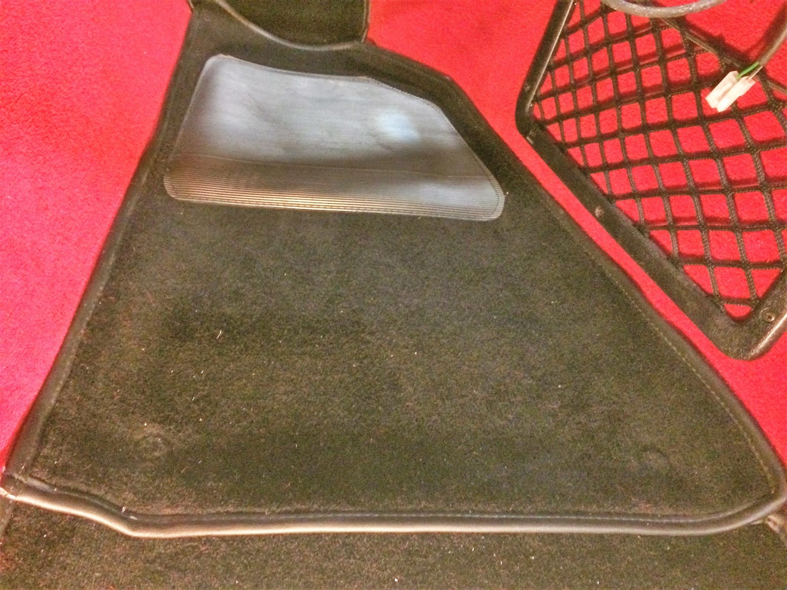
These tags are to stop the carpet moving. This is especially important on the driver's side. The fittings are made up of a press stud for the floor and two rings for the carpet.
One of the rings had three prongs (upper), the other has holes for the prongs to go through (under carpet). First I fixed the press stud parts to the floor using self tappers. I made sure that the studs were under the carpet and not the rubber heel pad.
Chalk was applied to the top of the press studs and transferred to the back of the carpet. The ring with the holes was placed on the underside of the carpet, over the chalk mark of the press stud. The ring with the prongs on the top side was lined up with the holes and the three prongs pushed through the carpet. The prongs were then tapped over the lower ring, trapping the carpet.
So the foot well carpets are now fixed down with the press studs.
Door card
I had never been happy with the passenger door card fitting. So I took the opportunity to refit it in the right location. It was only a few millimeters out, but I could see it.
Sorted the number plate light today. The bolt was not holding the chrome trim properly. I drilled out the supposedly threaded hole and fixed a rivnut. This sorted it out.
 |
| Rear number plate light fitting with rivnut |
Fog light wiring
For some reason I had not connected the three wires to the loom. Straight forward.
Foot well carpet securing tags
These tags are to stop the carpet moving. This is especially important on the driver's side. The fittings are made up of a press stud for the floor and two rings for the carpet.
 |
| The three parts to each fitting |
 |
| Press stud on floor |
 |
| Ring on underside of carpet |
 |
| Top pronged ring can be seen here - rubbing the carpet makes the ring almost disappear |
 |
| Passenger foot well carpet fixed |
I had never been happy with the passenger door card fitting. So I took the opportunity to refit it in the right location. It was only a few millimeters out, but I could see it.
Saturday, December 31, 2016
Dashboard electrics connection
Connecting the looms
There are two main black connectors on the dash board loom which can only fit one way in to the other half of the connector on the main body loom. Then there re two white connector blocks which link the dash loom to the body loom. Finally there is a white connector which has four earth (black) wires, which is again connected to the body loom.
The column wiring 'sub looms' connect to the dashboard loom in to the designated connectors. Again they will only go in to one connector.
The brake fluid warning wires (green and green/white) were fed through the bulkhead and connected to the brake fluid reservoir. Then the two wires that I had added for the auxiliary power socket were attached after small terminals had been attached.
Next the wires were attached to the ignition switch (see diagram from GD below).
Larger gauge wire crimp connectors (yellow) were needed for two of the wires. One of these needed a large 9.5 mm terminal too. See photo below.
Once all the connections had been made, it was time to test if the electrical items worked. That will follow shortly.
NOTE ADDED LATER: Take note of the "GD427 Mk4 Vauxhall column connections" document notes. These changes should ideally be made before the loom is put in place! A lot easier. Will post wiring changes later.
 |
| Spaghetti! |
 |
| The five connectors |
 |
| Column switch connections |
Next the wires were attached to the ignition switch (see diagram from GD below).
 |
| Lower right diagram shows how to connect the ignition switch |
 |
| Ignition switch connections |
NOTE ADDED LATER: Take note of the "GD427 Mk4 Vauxhall column connections" document notes. These changes should ideally be made before the loom is put in place! A lot easier. Will post wiring changes later.
Monday, December 26, 2016
Steering column - switches and wiring
This is the second part of my steering column switches and wiring post.
The switches were removed from the column mounting. The original stalks were cut off above the rubber gaitor locator towards the stalk end - see the photo below.
The end of the 'switch stalk' was then filed flat, drilled and tapped to take the replacement GD stainless stalks. The plastic flange that locates the rubber boot is at a slight angle, so the hole needed to be drilled to take account of this.
The new turned stalks were screwed in and a small amount of 'loctite' used to make sure they do not work loose. The column adjuster was fitted and a small grommet fitted to the leather to finish it off. This was glued to the leather to keep it in place.
The wires were connected to the column switches using the wiring diagram from GD. I will come on to the ignition switch later.
The wires have had female crimp connectors attached at the ends of the cut wires. Connectors are attached at the other end to link to the the dashboard loom using the block connector.
Don't push the switches fully home on the steering column at this stage, as they will need to be removed to install the dashboard.
The switches were removed from the column mounting. The original stalks were cut off above the rubber gaitor locator towards the stalk end - see the photo below.
 |
| Cut stalk alongside an in-cut one |
 |
| The plastic flange that the rubber boot is located on. Note that it is not 90 deg to the stalk |
 |
| New stalk fitted |
 |
| Wiring for column connectors |
 |
| A switch with the wires connected |
Thursday, December 01, 2016
Cobra power
Well electrical power I mean!
Power leads
The power leads have rubber caps put over their ends to cover the terminals and studs. IVA requires that there are no exposed power conductors where you could create a short. The studs were removed and Vaseline was applied to the end terminals to help get the rubber caps in place and reduce the risk of corrosion, and hence a bad connection. This was done for the live and earth in the battery compartment and for the power take off studs in the engine compartment. It was a fiddly and time consuming job, but it has to be done! Tip: If you have to do this try warming up the boots and apply Vaseline to the studs to help the boots slip in to place.
Fuel pump power
The fuel pump requires power. This achieved be using the thick red cable from the loom that has a ring terminal at it's end. Another hole needs drilling in the passenger footwell/bulkhead. A grommet was fitted, after thinning the GRP a little. This cable was then run through to the battery compartment and connected to the live feed from the battery.
Power leads
The power leads have rubber caps put over their ends to cover the terminals and studs. IVA requires that there are no exposed power conductors where you could create a short. The studs were removed and Vaseline was applied to the end terminals to help get the rubber caps in place and reduce the risk of corrosion, and hence a bad connection. This was done for the live and earth in the battery compartment and for the power take off studs in the engine compartment. It was a fiddly and time consuming job, but it has to be done! Tip: If you have to do this try warming up the boots and apply Vaseline to the studs to help the boots slip in to place.
 |
| Boots over cables in compartment |
 |
| Boots over studs in engine bay |
The fuel pump requires power. This achieved be using the thick red cable from the loom that has a ring terminal at it's end. Another hole needs drilling in the passenger footwell/bulkhead. A grommet was fitted, after thinning the GRP a little. This cable was then run through to the battery compartment and connected to the live feed from the battery.
Thursday, November 17, 2016
Auxiliary power supply
I fitted the nearside under dash tray today. A reverse of the driver's side, so it was easy, except I added a 12v power supply outlet.
Auxiliary power supply
The power outlet that I used was an Audi part that is used extensively by the VW group, so can be found in VW, Audi, Bentley cars etc. I bought mine from Prestige Motor Services (see link on right). This is a neat solution that hides under the nearside dash and can be closed when not in use. It pops down when needed and closes up when not needed. It avoids having the power outlet on show for example on the dashboard, which seems wrong for a Cobra - even a modern take on one like mine.
The power supply will go on the passenger side nearest the transmission tunnel. I had to take care marking out where the heater outlet and the power supply unit needed to fit, as they go between the two cross braces. An oblong was cut out of the under dash tray for the power unit. Here I drilled holes at each corner of the area to cut out, then I used a jig saw to cut out the hole, before finishing with a hand file. The aluminium was too thin for the power supply clips, so small pieces of aluminium (shims) were cut to pack out the clips (see photo below). These were glued in place.
Auxiliary power supply
The power outlet that I used was an Audi part that is used extensively by the VW group, so can be found in VW, Audi, Bentley cars etc. I bought mine from Prestige Motor Services (see link on right). This is a neat solution that hides under the nearside dash and can be closed when not in use. It pops down when needed and closes up when not needed. It avoids having the power outlet on show for example on the dashboard, which seems wrong for a Cobra - even a modern take on one like mine.
The power supply will go on the passenger side nearest the transmission tunnel. I had to take care marking out where the heater outlet and the power supply unit needed to fit, as they go between the two cross braces. An oblong was cut out of the under dash tray for the power unit. Here I drilled holes at each corner of the area to cut out, then I used a jig saw to cut out the hole, before finishing with a hand file. The aluminium was too thin for the power supply clips, so small pieces of aluminium (shims) were cut to pack out the clips (see photo below). These were glued in place.
 |
| Reverse of under dash tray showing small shims at either end of power unit |
 |
| Looking from foot well |
The wiring will be completed when I fit the dashboard.
Monday, November 14, 2016
Under dash trays and dashboard plus door seal finishers
At last, some work after a break doing some housework! Well work on the new house. So I am back to building the Cobra after almost a three month lay off. Yes I did a few small jobs, but now it's down to it properly.
Some essential, but easy jobs first. The bonnet was secured properly. The pivot bolts were re-attached, as were the gas struts. Next the remaining caphead bolts and washers were used to secure the hinges to the bonnet.
Then the wires were extended to attach to the horn. A tie wrap secured the wires to the compressor to ensure that they do not flap about.
Under dash trays
I have decided to replace the door seal finishers. I was not happy with those bought from Europa having seen the GD items. The GD finishers are not cheap, but they are good!
The rear door seal finishers will take a little more thinking about before I can fit them!
Some essential, but easy jobs first. The bonnet was secured properly. The pivot bolts were re-attached, as were the gas struts. Next the remaining caphead bolts and washers were used to secure the hinges to the bonnet.
Then the wires were extended to attach to the horn. A tie wrap secured the wires to the compressor to ensure that they do not flap about.
 |
| Wires tie wrapped to compressor |
I had already fitted the centre under dash tray (see a previous post) a while back. The centre tray is where the ECU will sit.
The outer trays were secured to the front cross brace (the brace nearest the bulkhead) using self tapping screws. This will allow access to the dash if needed, at a later date. I had been putting this off. I thought that dodging the swarf from drilling the holes would be difficult. It wasn't as the holes could be drilled without getting right under the dash, I simply leaned in to the footwell and drilled the holes.
The outer trays were fixed to the front brace only.
They were temporarily held at the dashboard end by racing tape. The trays will be sandwiched between the dashboard bottom and the rear most cross brace (nearest the driver/passenger).
The outer trays were secured to the front cross brace (the brace nearest the bulkhead) using self tapping screws. This will allow access to the dash if needed, at a later date. I had been putting this off. I thought that dodging the swarf from drilling the holes would be difficult. It wasn't as the holes could be drilled without getting right under the dash, I simply leaned in to the footwell and drilled the holes.
 |
| Hole in the underside of dash tray drilled through to the cross brace |
 |
| Under dash tray secured by self tapper |
The footwell heater outlet holes are pre-cut in the GD panels, but the laser cut holes were too small for the plastic vent, so needed opening out. I used the electric drill and a burr. Here one part of the vent pushes through the hole, securing with the flexible lugs. Two small slots in the trays and squares on the vent stop them swivelling. The other part clicks over the vent on the upper side.
The other side is handled in the same way.
Door seal finishers
 |
| Driver's side vent in place |
Door seal finishers
I have decided to replace the door seal finishers. I was not happy with those bought from Europa having seen the GD items. The GD finishers are not cheap, but they are good!
 |
| Front nearside door seal finisher in place |
Sunday, April 03, 2016
Dashboard - part 5
So the gauges were in place. Just a case of wiring up these gauges and the switches!
I had not considered that there was a standard layout for the gauges and that the dasboard loom was made for this. Because I had come up with my own layout, this meant that I had to chop quite a few tie wraps and extend some of the cables. Also the billet switches for the start and hazard lights had smaller terminals, so I had to source these connectors and replace the existing ones.
I am not installing a clock, so the wires provided in the loom for this were not needed. As the ETB gauges do not need a voltage stabiliser, there were a further three wires that were not used in the loom. I connected the light green wires designed for the stabilizer to the darker green wire, so that the 'stabilised' gauges had a normal ignition 12v power supply.
Next I puzzled the Lucas type switches for the lights and heater. Six terminals, but only five wires - so what goes where? Each of the terminals on the switches were marked with a number from 1 to 8 (3 and 5 were not used, hence six terminals). Here Noel Hirst and Keith Akerman helped clear up my confusion with some photos.
I had realised that in the loom there is a red/white wire for each switch which is the illumination and a black wire for each which is the ground for the illumination. As there is no illumination on these switches, these wires can be ignored/not used (needed to make sure that there was no risk of shorting). So each switch just had three wires connected in reality. The light switch was wired as follows: brown/blue to terminal 1, red terminal 4 and blue terminal 8. For the heater it was: green to terminal 4, green/slate terminal 6 and green/yellow terminal 8.
Oh, and the Canems immobiliser! This is fitted to the rear of the dashboard, close to the steering column on the right side when seen from the driver's seat so that the fob can de-activate it. The unit is about 50mm square and needs mounting with the plastic surround against the dash (flat on, not on it's edge). I had not allowed for this and it was very tight up against the hazard switch, so if you are doing this be aware! Plan ahe.. I had to trim away some of the dash around the steering column to allow it to fit.
I have decided to mount the remote trip/function push switch on the centre under dash cover. There is enough room to get your hand in between the lower part of the dash and the transmission tunnel to activate this. The remote switch comes with the ETB speedo and is part of the 'speedo loom'. This location saves having an additional item on the dashboard, which in my opinion, just clutters the thing. Some other makes of gauges have the trip switch on the face.
Apart from these issues, the wiring was fairly straight forward. I used the GD Dash Loom wiring diagram and the diagrams from ETB. Some of the wires were not used, so these were taped back on themselves, making sure that the conductors were not exposed. Others wires needed connecting to the GD loom, such as the speedo and tacho 'looms'. I have not given the full wiring, as this may differ depending on the gauges and switches used.
The column stalks have their own mini looms, which are not terminated at one of the ends. These mini looms connect into the relevant multiplug on the dashboard loom, but needed terminals adding to those wires that are used.
I had not considered that there was a standard layout for the gauges and that the dasboard loom was made for this. Because I had come up with my own layout, this meant that I had to chop quite a few tie wraps and extend some of the cables. Also the billet switches for the start and hazard lights had smaller terminals, so I had to source these connectors and replace the existing ones.
I am not installing a clock, so the wires provided in the loom for this were not needed. As the ETB gauges do not need a voltage stabiliser, there were a further three wires that were not used in the loom. I connected the light green wires designed for the stabilizer to the darker green wire, so that the 'stabilised' gauges had a normal ignition 12v power supply.
Next I puzzled the Lucas type switches for the lights and heater. Six terminals, but only five wires - so what goes where? Each of the terminals on the switches were marked with a number from 1 to 8 (3 and 5 were not used, hence six terminals). Here Noel Hirst and Keith Akerman helped clear up my confusion with some photos.
I had realised that in the loom there is a red/white wire for each switch which is the illumination and a black wire for each which is the ground for the illumination. As there is no illumination on these switches, these wires can be ignored/not used (needed to make sure that there was no risk of shorting). So each switch just had three wires connected in reality. The light switch was wired as follows: brown/blue to terminal 1, red terminal 4 and blue terminal 8. For the heater it was: green to terminal 4, green/slate terminal 6 and green/yellow terminal 8.
Oh, and the Canems immobiliser! This is fitted to the rear of the dashboard, close to the steering column on the right side when seen from the driver's seat so that the fob can de-activate it. The unit is about 50mm square and needs mounting with the plastic surround against the dash (flat on, not on it's edge). I had not allowed for this and it was very tight up against the hazard switch, so if you are doing this be aware! Plan ahe.. I had to trim away some of the dash around the steering column to allow it to fit.
 |
| Immobiliser unit against steering column hole |
Apart from these issues, the wiring was fairly straight forward. I used the GD Dash Loom wiring diagram and the diagrams from ETB. Some of the wires were not used, so these were taped back on themselves, making sure that the conductors were not exposed. Others wires needed connecting to the GD loom, such as the speedo and tacho 'looms'. I have not given the full wiring, as this may differ depending on the gauges and switches used.
 |
| Spaghetti! |
 |
| Terminals added to column connection multi-plugs |
Tuesday, March 22, 2016
Engine sensors fitted
So the instruments have arrived. Now I needed to fit the engine sensors.
First was the oil pressure sensor. Not straight forward! I had to loosen the plenum first so that the sensor would fit. Without this being removed the sensor was too wide at the base. The sensor is fitted in to the M16 to 1/8" NPT adapter. I had to tighten the adapter to the sensor first, before I used grips to gently tighten the sensor in the hole. The wire to the loom was then attached.
Next came the water temperature sensor. This is fitted to the back of the off side head and there is little space! The back spark plug connection was removed to give a little more space. The adapter was again fitted to the sensor, before tightening in the head. Finally the loom wire was attached.
Finally the oil temperature sensor was fitted. For a change this was easy. Accessing the oil filter housing from under the car, the adapter - pre-fitted to the sensor, was screwed in place then tightened and the loom wire attached. NOTE: Do make sure that the sensors are tightened - I hadn't!
Now, whilst in the engine compartment I did a couple of small jobs. First, I am embarrassed to say, was to swap the rocker covers around. I had re-fitted them on the wrong sides. D'oh! Not that it matters that much, but I had decided that it would be easier to fill with oil if the filler was on the off-side. This required the coils and plug lead assembly to be removed from the covers and re-fitted to the correct cover. The fitting of the vacuum pipe had to be modified slightly too.
Next came the washer bottle connection. The water tube was fed through the lower hole in the bulkhead (after fitting a grommet) and connected to the outlet on the washer pump. The two wires were also fed through the hole and connected to the pump.
Just to fill in the time I set up the dash with the steering wheel to check if I could see all the warning lights and gauges - I couldn't, so have moved a few things round. So here is how it looks at present. The GRP panel will need some fettling to avoid the hinges binding and to closely follow the scuttle contour, whilst allowing for the leather trim.
First was the oil pressure sensor. Not straight forward! I had to loosen the plenum first so that the sensor would fit. Without this being removed the sensor was too wide at the base. The sensor is fitted in to the M16 to 1/8" NPT adapter. I had to tighten the adapter to the sensor first, before I used grips to gently tighten the sensor in the hole. The wire to the loom was then attached.
 |
| Oil pressure sensor in place. Spare terminal is for an oil warning light. |
 |
| Water temperature sensor fitted |
 |
| Oil temperature sensor fitted |
 |
| Rocker covers right way round. Note filler on left of photo. |
 |
| Water tube and wiring |
 |
| Revised dash layout after loosely fitting the wheel |
Subscribe to:
Posts (Atom)