I finished off polishing the Cobra today. At first by hand, then by machine using a lambs wool bonnet. Looks good, a real shine to it.
I have asked Andy at GD to install a new brake pipe to replace the damaged one, when the car goes to him for checking over and the IVA test.
Now it is a case of twiddling my thumbs until the car is collected for the IVA. What will I do with all my time - no car, no blog ........ I am sure that my wife has plenty of ideas!

Dale's Gardner Douglas 427 mk4 Building an AC Cobra re-creation
Showing posts with label Brakes. Show all posts
Showing posts with label Brakes. Show all posts
Tuesday, January 31, 2017

Saturday, January 28, 2017
Bleeding brakes!
Brakes
There was a weep where the copper pipe/brass union joined the central (rear brakes) master cylinder. There may not have been much of a weep, but with brakes you don't mess around. To inspect this I had to drain the brake fluid from the reservoir and pipes above the rear master cylinder - messy! Here I attached a plastic tube to the nipples of both rear callipers (separately). I then opened each nipple to drain the fluid from the pipes, as if bleeding the brakes, and the reservoir. The Eezibleed system was used to put some pressure in to the reservoir and pipes to flush out the brake fluid.
Once this was done, the rubber pipe that feeds the reservoir and the copper brake pipe were removed and inspected. I could see a small score on the copper brake pipe flare. Then I noticed two cracks in the brass union. No wonder it was leaking! I had probably tightened it too much to cure the weep from the flare in the copper pipe. Unfortunately I don't have a spare union or section of brake pipe to make another. I cleaned the master cylinder union hole with a cotton wool bud dipped in acetone, to get rid of any oil, then conceded defeat.
So I need to speak to Andy on Monday morning and ask him to fit a new union and pipe when the car comes down for checking over. As a result the handbrake cannot be finalised, so another job for Andy.
Polishing
Because I couldn't do any more work on the brakes, I turned my attention to cleaning the car. After vacuuming it out, I used Simonize carnauba wax on the body. Not the easiest stuff to put on and take off, but a great shine. Managed half the car before I got bored. Will do the rest tomorrow.
There was a weep where the copper pipe/brass union joined the central (rear brakes) master cylinder. There may not have been much of a weep, but with brakes you don't mess around. To inspect this I had to drain the brake fluid from the reservoir and pipes above the rear master cylinder - messy! Here I attached a plastic tube to the nipples of both rear callipers (separately). I then opened each nipple to drain the fluid from the pipes, as if bleeding the brakes, and the reservoir. The Eezibleed system was used to put some pressure in to the reservoir and pipes to flush out the brake fluid.
Once this was done, the rubber pipe that feeds the reservoir and the copper brake pipe were removed and inspected. I could see a small score on the copper brake pipe flare. Then I noticed two cracks in the brass union. No wonder it was leaking! I had probably tightened it too much to cure the weep from the flare in the copper pipe. Unfortunately I don't have a spare union or section of brake pipe to make another. I cleaned the master cylinder union hole with a cotton wool bud dipped in acetone, to get rid of any oil, then conceded defeat.
So I need to speak to Andy on Monday morning and ask him to fit a new union and pipe when the car comes down for checking over. As a result the handbrake cannot be finalised, so another job for Andy.
Polishing
Because I couldn't do any more work on the brakes, I turned my attention to cleaning the car. After vacuuming it out, I used Simonize carnauba wax on the body. Not the easiest stuff to put on and take off, but a great shine. Managed half the car before I got bored. Will do the rest tomorrow.
Sunday, January 15, 2017
Not a good day in the garage today
Coolant
No visible signs of leaks. Good news.
Engine
No visible oil leaks either. So I removed the plugs ready to turn the engine over and get oil pressure. The 8 plugs are really difficult to get at and were not easy to remove.
And it went downhill from here.
Tried to turn over the engine - switched on the ignition and hit the starter button. Nothing! I then connected the fuel pump wire to the battery in case there was any electrical connection here. Still nothing. Will sleep on that.
Fuel
Put some unleaded in the tank and no leaks. Good start. But no fuel pump sound. Urghhhh.
Brakes
Jacked up the car. Connected the Eezibleed system to the reservoir and a tyre (gets pressure from here which allows you to do it on your own). The new cap leaked - easy enough to solve, I thought. So I rescued the old one from the bin! Bin diving is not a lot of fun. Fitted the old cap and great no leaks from the reservoir, but ........
Bled the rear brakes whilst keeping an eye on the brake fluid container and the reservoir. Then I noticed a great big puddle of brake fluid at the front! It was coming from a master cylinder where it joined the brake pipe. At first it was just dripping in to the off-side compartment, but then it started running out through some holes and on to the garage floor, which is when I noticed it.
Cleaned up. Packed up. Fed up!
No visible signs of leaks. Good news.
Engine
No visible oil leaks either. So I removed the plugs ready to turn the engine over and get oil pressure. The 8 plugs are really difficult to get at and were not easy to remove.
And it went downhill from here.
Tried to turn over the engine - switched on the ignition and hit the starter button. Nothing! I then connected the fuel pump wire to the battery in case there was any electrical connection here. Still nothing. Will sleep on that.
Fuel
Put some unleaded in the tank and no leaks. Good start. But no fuel pump sound. Urghhhh.
Brakes
Jacked up the car. Connected the Eezibleed system to the reservoir and a tyre (gets pressure from here which allows you to do it on your own). The new cap leaked - easy enough to solve, I thought. So I rescued the old one from the bin! Bin diving is not a lot of fun. Fitted the old cap and great no leaks from the reservoir, but ........
Bled the rear brakes whilst keeping an eye on the brake fluid container and the reservoir. Then I noticed a great big puddle of brake fluid at the front! It was coming from a master cylinder where it joined the brake pipe. At first it was just dripping in to the off-side compartment, but then it started running out through some holes and on to the garage floor, which is when I noticed it.
Cleaned up. Packed up. Fed up!
Monday, May 30, 2016
ABCDE of Cobra building!
Accelerator
I have a fly by wire accelerator pedal, so the loom has provision for this. I drilled the holes for the fitting plate and a hole big enough to allow the connector to pass through. This was attached with M5 button head bolts and nyloc nuts. The plate was made by Keith Akerman, fabulous piece of engineering, as expected from him.
Brake and Clutch hoses
The hoses needed securing so as to comply with IVA requirements. Again a part made by Keith came in to play to secure the three braided hoses against the side of the engine bay. Another pair of hands was needed to fix this wit M4 screws, so Carol came to my rescue. A P-clip was used to secure the hoses to the reservoir.
Dipstick tube
This had bugged me for a while! So I thought that I had better sort it. The dipstick tube was the wrong shape for the LS6 engine. So using a pipe bender, I carefully reshaped the tube to avoid the headers and HT leads. Once it was the right shape, the tube was secured with a P-clip to the coil frame, after adding some rubber tubing to make sure that the tube would not move. It was fairly easy really. Don't know why I had kept putting it off.
Foot well Extension
Now it was time to fit the foot well extension. Again Carol helped, as my arms were not long enough. The extension was simply bolted in place, where it had been trial fitted before. I did apply some silicone to make sure it was sealed, both inside and out.
I have a fly by wire accelerator pedal, so the loom has provision for this. I drilled the holes for the fitting plate and a hole big enough to allow the connector to pass through. This was attached with M5 button head bolts and nyloc nuts. The plate was made by Keith Akerman, fabulous piece of engineering, as expected from him.
 |
| Accelerator pedal with connection made. Note split plate and grommet. |
The electrical connector was pushed on to the pedal until it clicked. Easy!
The hoses needed securing so as to comply with IVA requirements. Again a part made by Keith came in to play to secure the three braided hoses against the side of the engine bay. Another pair of hands was needed to fix this wit M4 screws, so Carol came to my rescue. A P-clip was used to secure the hoses to the reservoir.
 |
| Hoses secured |
This had bugged me for a while! So I thought that I had better sort it. The dipstick tube was the wrong shape for the LS6 engine. So using a pipe bender, I carefully reshaped the tube to avoid the headers and HT leads. Once it was the right shape, the tube was secured with a P-clip to the coil frame, after adding some rubber tubing to make sure that the tube would not move. It was fairly easy really. Don't know why I had kept putting it off.
 |
| Dipstick fitted and secured to coil frame |
Now it was time to fit the foot well extension. Again Carol helped, as my arms were not long enough. The extension was simply bolted in place, where it had been trial fitted before. I did apply some silicone to make sure it was sealed, both inside and out.
 |
| Not the prettiest of jobs, but hopefully effective |
Sunday, February 28, 2016
A little more progress!
I only managed a couple of hours in the garage this afternoon, but nevertheless a small amount of progress.
Speed sensor
Handbrake
I finished off the handbrake too. Tied in the cable to the chassis.
Then siliconed around the grommet to avoid water ingress.

Under boot supports
On the Euro there are two plates that are fitted under the rear of the chassis. These help to take the extra weight that you may put in the boot. There are three rivnuts on each side for this purpose.
First two pieces of self adhesive sponge rubber are fitted to each of the plates. The plates are then bolted in place and tightened, squashing the rubber.
I managed to cross thread one of the rivnuts on the nearside, so now the it turns in the chassis rail. I will need to work out how to get the bolt out! But that is for another day.
Fuel tank
Sponge rubber was stuck to the fuel tank - two strips along the back and one underneath. I also added sound deadening sheets to reduce the chance of hearing fuel sloshing around.
Speed sensor
Tightened the bolt that I forgot yesterday! I had only put it in finger tight, whilst I sorted out the wires. An important, but small job, to avoid the sensor falling out!
Handbrake
I finished off the handbrake too. Tied in the cable to the chassis.
 |
| Tie wrapped handbrake cable |

Under boot supports
On the Euro there are two plates that are fitted under the rear of the chassis. These help to take the extra weight that you may put in the boot. There are three rivnuts on each side for this purpose.
 |
| Three rivnuts on rear underside of chassis |
 |
| Boot support plate |
Fuel tank
Sponge rubber was stuck to the fuel tank - two strips along the back and one underneath. I also added sound deadening sheets to reduce the chance of hearing fuel sloshing around.
 |
| Fuel tank with sponge rubber and sound deadening panels |
Friday, February 26, 2016
Engine loom part 2
Final bit of engine loom sorted today. If you are building a GD427, then do connect up the loom before you put the body on. Or at least connect up the loom to the gearbox and starter motor. It is so much easier to do it at that stage.
Reverse lights
The reverse light switch on the gearbox had two wires. These were now tucked away alongside the gearbox and within the chassis. So after jacking the car well up at the front and crawling under it, hands shredded, I finally managed to connect the bullet connectors together. Not the easiest or most pleasant of jobs.
Speed sensor
The speed sensor was in theory simple too. The car was jacked up well at the side. After crawling under the car, I managed to get my hand into the transmission tunnel at the back of the gearbox and remove the sensor, which was held in by one bolt and a locating plate.
The two wires were attached to the sensor using two thin connectors out of a waterproof Delphi double connector! The waterproof seals and some silicone were used to make sure that the connectors stayed in place and kept dry.
The installation was a reverse of the previous process. Don't lower the car until you have tightened the bolt :) Just don't expect this to be easy to get at!
Starter motor
Another nightmare to get at! The starter motor is tucked up behind the exhaust headers, with the solenoid on top.
The thick red wire from the battery and the red wire from the loom marked 'starter' are connected to the lower thick terminal. The other wire, slate and red, is connected to the thinner stud on the solenoid. The small wire terminal will not go on the wrong stud.
Bulkhead 'grommet'
A very rewarding job. Nice finisher!
An aluminium two piece bulkhead grommet had been machined by Keith Akerman for his car and I managed to get one from him, a real work of art!
GD don't do a part for this. It was easily fitted around the loom and pushed through the bulkhead. The bulkhead hole needed a bit of filing to open it out, before fixing the 'grommet' with four buttonhead bolts. A very neat solution and much better than having to fabricate one myself.
Fuel pump
The short wire on the loom marked 'Pump' was connected to the white/purple wire of the body loom. This went to the fuse box, so needed cutting from the fuse box. The body loom is designed for a non-LS engine car, which has a different pump arrangement. A male connector was added to the cut wire and then connected to the wire on the relay block. See photo below where the cut wire can just be seen coming out of the fuse box and is taped up in black.
The relay block will be attached to one of the underdash trays later.
So now I just have the sensors to connect up on the engine - oil pressure, oil temperature and water temperature for the gauge, when I get them. All easy to get at. Well relatively .....
Thermostat
Luckily I realised that there was no thermostat in the housing, thanks for telling me Kyle, so I bought one from Monkfish. Great service and very prompt delivery. Whilst I was at it, I replaced the seal.
It was simply a case of undoing two bolts on the housing, replacing the seal and inserting the thermostat, then putting the bolts back in place.
Header tank hose
At this stage the handbrake could not be adjusted as it is a hydraulic/mechanical handbrake, so the brake fluid needs adding and bleeding first. However, the handbrake cable could be secured to the chassis with tie wraps, to keep it away from moving parts.
The carpet will be cut later, once the gaiter is received and fitted.
Gear lever
This was simply a case of attaching the lever with two bolts into the threaded gear lever stub on the 'box and then securing with nylocs. Once in place, I opened out the transmission tunnel hole slightly with the Dremel so that it would not foul against the GRP. Now I can select gears!!
Reverse lights
The reverse light switch on the gearbox had two wires. These were now tucked away alongside the gearbox and within the chassis. So after jacking the car well up at the front and crawling under it, hands shredded, I finally managed to connect the bullet connectors together. Not the easiest or most pleasant of jobs.
 |
| Lacerations |
The speed sensor was in theory simple too. The car was jacked up well at the side. After crawling under the car, I managed to get my hand into the transmission tunnel at the back of the gearbox and remove the sensor, which was held in by one bolt and a locating plate.
The two wires were attached to the sensor using two thin connectors out of a waterproof Delphi double connector! The waterproof seals and some silicone were used to make sure that the connectors stayed in place and kept dry.
 |
| Speed sensor with wires siliconed in place |
Starter motor
Another nightmare to get at! The starter motor is tucked up behind the exhaust headers, with the solenoid on top.
 |
| Starter motor wires in place |
Bulkhead 'grommet'
A very rewarding job. Nice finisher!
An aluminium two piece bulkhead grommet had been machined by Keith Akerman for his car and I managed to get one from him, a real work of art!
 |
| Components of bulkhead grommet |
 |
| Neat! |
The short wire on the loom marked 'Pump' was connected to the white/purple wire of the body loom. This went to the fuse box, so needed cutting from the fuse box. The body loom is designed for a non-LS engine car, which has a different pump arrangement. A male connector was added to the cut wire and then connected to the wire on the relay block. See photo below where the cut wire can just be seen coming out of the fuse box and is taped up in black.
 |
| Fuel pump wires sorted |
So now I just have the sensors to connect up on the engine - oil pressure, oil temperature and water temperature for the gauge, when I get them. All easy to get at. Well relatively .....
Thermostat
Luckily I realised that there was no thermostat in the housing, thanks for telling me Kyle, so I bought one from Monkfish. Great service and very prompt delivery. Whilst I was at it, I replaced the seal.
 |
| New thermostat and seal |
 |
| Where the thermostat goes |
A new piece of hose was attached between the block and the header tank (because I had originally used vacuum tube - not a good idea!).
 |
| Correct hose! |
Handbrake
The handbrake was attached to the bracket to allow me to locate the position of the fixing holes. The end of the handbrake (the end with the button) was positioned in line with the front of the door opening. The holes in the mounting plate were marked through onto the floor and drilled. Bolts went through the bracket and through the holes in the floor. The bolts were secured with nuts and shakeproof washers on the underside of the car, using large washers to spread the load.
 |
| Handbrake in place |
The carpet will be cut later, once the gaiter is received and fitted.
Gear lever
This was simply a case of attaching the lever with two bolts into the threaded gear lever stub on the 'box and then securing with nylocs. Once in place, I opened out the transmission tunnel hole slightly with the Dremel so that it would not foul against the GRP. Now I can select gears!!
 |
| Gear lever. Escutcheon is only laid in place. |
Tuesday, February 16, 2016
Carpets, handbrake cable and belt mounts
Carpets
The transmission tunnel was cleaned with acetone, then the loom was taped over using racing tape. The carpet was then fed under the cross brace and the screws inserted through the feet on the cross brace to screw into the rivnuts that I had fitted earlier. At this stage I did not tighten down or fit the packing washers. A small cut was then made to allow the gear selector stub to poke through.
Andy at GD had advised me to use spray adhesive, as it would be easier to remove the carpets if they became wet. I did not tell him that Cobra owners did not take their cars out in the rain! However, noting his advice I sprayed the section of the tunnel top from the cross brace to the gear lever and the corresponding part of the carpet with adhesive. Then after a few minutes I carefully brought the two together, making sure they were lined up. The rest of the tunnel top and carpet were then sprayed and after a while, brought together. The carpet below the dash was not glued.
Next the carpet at the sides of the tunnel and the sides of the tunnel itself were sprayed with the adhesive in sections and brought together, smoothing down as I went. The body bolts were not glued over, so that I had access if I need it at a later date (hopefully I won't need this!). The excess carpet down the sides of the transmission tunnel near the rear bulkhead was trimmed off. At this stage, the drivers footwell area was not stuck down (I need to trim around the footwell extension). The gear lever hole was cut out of the carpet using the edge of the gear shift hole as a guide.
The floor carpets were loose laid and the vertical carpet (side and rear bulkhead) was trimmed (ran onto the floor of the car).
Handbrake (park brake)
A 20 mm hole was drilled behind the drivers seat in the rear bulkhead, near to the wheel arch at floor level for the handbrake cable. The hole was slightly larger than really required for the cable, but was made to take the grommet that I used. The GRP around the hole required thinning a little to allow the grommet to be fitted.
The grommet was pushed over the cable, then the cable was fed through the hole in to the cockpit area. The grommet will be sealed in place with silicone at a later date.
More carpet
Now the rear bulkhead carpet was ready to fix. The same technique was used to stick this carpet down. I laid out the carpet and applied adhesive to the centre area of the bulkhead and to one of the outer sides only and to the same area of the carpet. After allowing it to go tacky, this was fixed in place, making sure that the outer pieces lay in the correct places.
Finally the other outer part of the bulkhead carpet was glued in place after it was cut around the handbrake cable.
Lower seatbelt fasteners
I am fitting 4 point harnesses to the car, so 50 mm eye bolts were fitted through 11 mm holes in the floor, but these had to be ground down by 15 mm in length (leave two threads showing for the IVA). The top seat belt mounts will be on the roll over hoops. The holes in the carpets were created by running the drill in the reverse direction to avoid twisting the carpet. The bolts, with washers, were fed through the carpet and retained under the car by stress plates with the nuts welded in place. The plates were located with self tapping screws. This type of fixing are ok for the IVA, but if you are using separate nuts fit spring washers to avoid the risk of working loose.
The transmission tunnel was cleaned with acetone, then the loom was taped over using racing tape. The carpet was then fed under the cross brace and the screws inserted through the feet on the cross brace to screw into the rivnuts that I had fitted earlier. At this stage I did not tighten down or fit the packing washers. A small cut was then made to allow the gear selector stub to poke through.
Andy at GD had advised me to use spray adhesive, as it would be easier to remove the carpets if they became wet. I did not tell him that Cobra owners did not take their cars out in the rain! However, noting his advice I sprayed the section of the tunnel top from the cross brace to the gear lever and the corresponding part of the carpet with adhesive. Then after a few minutes I carefully brought the two together, making sure they were lined up. The rest of the tunnel top and carpet were then sprayed and after a while, brought together. The carpet below the dash was not glued.
Next the carpet at the sides of the tunnel and the sides of the tunnel itself were sprayed with the adhesive in sections and brought together, smoothing down as I went. The body bolts were not glued over, so that I had access if I need it at a later date (hopefully I won't need this!). The excess carpet down the sides of the transmission tunnel near the rear bulkhead was trimmed off. At this stage, the drivers footwell area was not stuck down (I need to trim around the footwell extension). The gear lever hole was cut out of the carpet using the edge of the gear shift hole as a guide.
 |
| Carpet glued to transmission tunnel |
Handbrake (park brake)
A 20 mm hole was drilled behind the drivers seat in the rear bulkhead, near to the wheel arch at floor level for the handbrake cable. The hole was slightly larger than really required for the cable, but was made to take the grommet that I used. The GRP around the hole required thinning a little to allow the grommet to be fitted.
 |
| Brake cable fed through grommet |
More carpet
Now the rear bulkhead carpet was ready to fix. The same technique was used to stick this carpet down. I laid out the carpet and applied adhesive to the centre area of the bulkhead and to one of the outer sides only and to the same area of the carpet. After allowing it to go tacky, this was fixed in place, making sure that the outer pieces lay in the correct places.
Finally the other outer part of the bulkhead carpet was glued in place after it was cut around the handbrake cable.
 |
| Rear bulkhead carpet |
I am fitting 4 point harnesses to the car, so 50 mm eye bolts were fitted through 11 mm holes in the floor, but these had to be ground down by 15 mm in length (leave two threads showing for the IVA). The top seat belt mounts will be on the roll over hoops. The holes in the carpets were created by running the drill in the reverse direction to avoid twisting the carpet. The bolts, with washers, were fed through the carpet and retained under the car by stress plates with the nuts welded in place. The plates were located with self tapping screws. This type of fixing are ok for the IVA, but if you are using separate nuts fit spring washers to avoid the risk of working loose.
 |
| Seat belt eye bolts, with handbrake cable over the carpet |
 |
| Stress plates for seat belts under the car |
Monday, January 04, 2016
Small but important jobs
Loads of small jobs to do. Feels great to knock them off the list!
Coil packs
Re-fitted the plug leads and coil packs today. I have fixed the brackets to the rocker covers using M6 16 mm button head screws. The holes in the rocker covers that were not used had M6 12 mm button heads inserted to finish them off.
Exhaust clamps
I was not happy with the front and middle exhaust clamps. They hung down too low and so would reduce ground clearance and the exposed threads were an invitation to make contact with the road. Even if I twisted them around, I couldn't gain much ground clearance without coming into contact with the chassis. As we have quite high speed bumps on our road (higher than the legal limit of 4"), I needed to make sure that the ground clearance was as high as possible.
I bought four Mikalor exhaust clamps from Westfield Fasteners to replace the standard clamps. Not cheap at £18 plus p&p, but worth the outlay. The photo above shows the before view and below shows the after views.
Gearbox mount bolts
Replaced the two bolts gearbox mount bolts with 10.9 grade bolts. The others had lost there edge from being put in, thread locked and taken out a few times.
Brace bars and cooling
I refitted the front brace bars, the radiator support frame and the radiator. This should have been really easy, but for some reason the bolts took some inserting in the brace bars, before fixing with nyloc nuts.
Once the radiator support frame was in place, I trial fitted the header tank and hoses. This was an easy job and very intuitive. I have used black silicone hoses with W4 clamps (stainless steel). I replaced the supplied air intake zinc plated clamps with four 100 mm W4 clamps. The radiator will have to come off for the fan to be fitted.
Coil packs
Re-fitted the plug leads and coil packs today. I have fixed the brackets to the rocker covers using M6 16 mm button head screws. The holes in the rocker covers that were not used had M6 12 mm button heads inserted to finish them off.
 |
| Coils and plug leads fitted |
I was not happy with the front and middle exhaust clamps. They hung down too low and so would reduce ground clearance and the exposed threads were an invitation to make contact with the road. Even if I twisted them around, I couldn't gain much ground clearance without coming into contact with the chassis. As we have quite high speed bumps on our road (higher than the legal limit of 4"), I needed to make sure that the ground clearance was as high as possible.
 |
| Standard brackets hang down too far |
 |
| Almost flat clamps (Mikalor) |
 |
| Front clamps fitted |
Replaced the two bolts gearbox mount bolts with 10.9 grade bolts. The others had lost there edge from being put in, thread locked and taken out a few times.
 |
| New gearbox mount bolts |
I refitted the front brace bars, the radiator support frame and the radiator. This should have been really easy, but for some reason the bolts took some inserting in the brace bars, before fixing with nyloc nuts.
 |
| Brace bars, radiator support frame and radiator in place |
 |
| Hoses and header tank trial fitted |
Idler pulley
The idler pulley is not used on the GD, so I removed the bracket and pulley.
Clutch hydraulics
 |
| Idler pulley on right |
 |
| Idler pulley removed |
Transmission tunnel cover
The transmission tunnel cover needed a hole cutting out for the gear shifter. First I marked this out by measuring the position of the shifter, then drawing a circle 65 mm in diameter. My chassis is a Euro, so the sponge rubber was in place, therefore the hole was cut from the bottom side of the panel.
Put away the Dremel for this job. I broke a cutting bit. The hole was cut out using a jig saw and then tidied up with a half round file.
 |
| Hole cut in transmission tunnel cover |
A smear of Loctite 572 was applied to the clutch pipe connectors (there are four surfaces to be treated) before they were connected to the block. The block was dismantled to allow the pipe connectors to be nipped up. The rigid brake pipes from the chassis were already in place.
The two braided clutch pipes were strapped together with a couple of plastic tie wraps.
So a load of easy/small jobs done and out of the way.
 |
| From left to right clutch bleed, clutch feed, brake pipes x 2 |
So a load of easy/small jobs done and out of the way.
Sunday, November 15, 2015
Brake and clutch pipes
The brake and clutch master cylinders had been fixed in place and so had the flexible braided hoses that will connect the body to the chassis union. The positions on the chassis connection block are nicely etched on from what I have seen. The silicone hoses that link the reservoirs to the master cylinders were also in place, but as yet not connected. So 'all' that was required was to connect them. Easy ..... or so I thought!
The 'output' braided hoses (pressure) had already been attached to the inner wing using the three 10 mm holes and the 'input' silicone hoses (from the reservoirs) had been fed through the three 15 mm holes I had drilled earlier in the inner wing between the engine bay and the compartment behind the wheel arch. The input and output hoses had been installed in the following sequence (from the front of the car):
Brake pipes
Now read this carefully and take on board. I hadn't!
I had initially tried to connect the unions pre-fitted to the brake pipes to the front ports, assuming that the input pipe would go to the rear ports, like the clutch cylinder. After a conversation with Andy, who was totally confused with what I was doing, it turned out that I had been trying to fit the Jaguar unions in to the two master cylinders that had been supplied. Andy thought that he had explained what was needed to me, hence the confusion.
The rear ports are actually 3/8 UNF and take the pressure pipes. The front are 7/16 UNF and take the silicone input pipes from the reservoir, via brass hosetails.
I had not appreciated the correct fitting or the changes required. So the brake pipes had been bent before I realised that the fittings on the pipes were wrong and that I was trying to fit them in the wrong holes!
I didn't have any of the unions which should have come with the brake pipes/cylinders. After the conversation and a few photos by emails, Andy at GD put me on the right path and sent me the missing parts.
The unions on the pipes supplied by GD, No. 11 and 12, needed changing to the 3/8 UNF unions (the bottom two in the picture above). My flaring tool kit came in useful for this (the pipes were originally for the Jaguar tandum master cylinder which uses M10 and M12 connectors, my car has two separate brake cylinders connected via a balance bar). Are you still following this?
So with the correct fittings on the copper pipes and the brass tails for the silicone hose I started again.
Remember that the brake pipes are attached to the rear output holes. This is the reverse of the clutch master cylinder just to make things more interesting. The copper brake pipe was re-bent and attached, so that each pipe linked the cylinders to the appropriate braided hose previously fitted. I found that attaching the pipes to the master cylinder first, then to the braided hose fittings on the inner wings was the easiest method to avoid cross threading (loosen the nuts on the braided hose first).
The silicone hoses were then connected to the new brass hosetails (remember to use the supplied Dowty washers - the ones with rubber around the inside) on the front of each brake cylinder. The hoses were clamped in place with pipe clips.
The 'output' braided hoses (pressure) had already been attached to the inner wing using the three 10 mm holes and the 'input' silicone hoses (from the reservoirs) had been fed through the three 15 mm holes I had drilled earlier in the inner wing between the engine bay and the compartment behind the wheel arch. The input and output hoses had been installed in the following sequence (from the front of the car):
- Front brakes
- Rear brakes
- Clutch
- Front brakes - 0.75" cylinder
- Rear brakes - 0.625" cylinder
- Clutch
The copper clutch pipe was identified in the GD kit (it was the shortest one marked No. 10 on the yellow sleeve). The silicone hose from the clutch reservoir to the clutch master cylinder, was connected to the white plastic hosetail, using a pipe clip to secure it. The plastic union was removed from the master cylinder to make this a bit easier. The copper clutch pressure pipe was bent so that it fit between the front of the clutch master cylinder and the rear braided output hose (see blow).
 |
| Clutch master cylinder with connections made |
Now read this carefully and take on board. I hadn't!
I had initially tried to connect the unions pre-fitted to the brake pipes to the front ports, assuming that the input pipe would go to the rear ports, like the clutch cylinder. After a conversation with Andy, who was totally confused with what I was doing, it turned out that I had been trying to fit the Jaguar unions in to the two master cylinders that had been supplied. Andy thought that he had explained what was needed to me, hence the confusion.
The rear ports are actually 3/8 UNF and take the pressure pipes. The front are 7/16 UNF and take the silicone input pipes from the reservoir, via brass hosetails.
I had not appreciated the correct fitting or the changes required. So the brake pipes had been bent before I realised that the fittings on the pipes were wrong and that I was trying to fit them in the wrong holes!
I didn't have any of the unions which should have come with the brake pipes/cylinders. After the conversation and a few photos by emails, Andy at GD put me on the right path and sent me the missing parts.
 |
| The brake unions |
 |
| The bent brake pipes plus the unions that need swapping |
Remember that the brake pipes are attached to the rear output holes. This is the reverse of the clutch master cylinder just to make things more interesting. The copper brake pipe was re-bent and attached, so that each pipe linked the cylinders to the appropriate braided hose previously fitted. I found that attaching the pipes to the master cylinder first, then to the braided hose fittings on the inner wings was the easiest method to avoid cross threading (loosen the nuts on the braided hose first).
 |
| Copper pressure pipes attached to the rear ports |
 |
| Silicone hoses from the reservoirs in place
Now, when Andy checks the brakes before the IVA test, he may need to swap the master cylinders around to get the correct pressure at the back and front!
NOTE: This wasn't required, but the balance was corrected as expected. |
Tuesday, October 20, 2015
Accelerator and clutch pedals
I tackled the accelerator and clutch pedals today.
Accelerator pedal
The accelerator pedal had too little travel - about 80mm when it should have been 100mm. This would have made the engine react quicker, but getting older I thought that I should set it as GD had recommended! The issue was that the linkage to the fly-by-wire pedal was set 10mm down from the top of the accelerator pedal (as per GD advice), but as a result the leverage was too little.
I had spoken to Keith Akerman and he had set his at 45mm using a clamp mechanism - mine was drilled, so had no adjustment. I decided, after playing about, that about 43mm would be ok. So I drilled another 6mm hole 43mm down from the top of the pedal. The original hole in the top of the pedal was left. The hole for the connecting bar needed opening up a little to allow the bar to function without fouling the bulkhead. After adjusting the rose joints on the bar, I got 100mm of travel on the pedal! Job done.
Clutch pedal
Next was the clutch pedal and cylinder. The clutch cylinder needed fixing to the bulkhead, but had to be mounted off it to allow the cylinder to function correctly. GD had supplied longer bolts for this. I spaced out the cylinder with washers and found that 8mm was about right. Sounds easy, but it took an age.
The clevis was then attached to the push rod and adjusted to set the pedal at the correct height. Take care here not to have the clutch partly disengaged/depressed, as the clutch will spin up under load. This can be adjusted with the clevis fixed to the pedal, by rotating the push rod. The clevis locking plate was attached to secure the clevis to the pedal. Another job done!
Accelerator pedal
The accelerator pedal had too little travel - about 80mm when it should have been 100mm. This would have made the engine react quicker, but getting older I thought that I should set it as GD had recommended! The issue was that the linkage to the fly-by-wire pedal was set 10mm down from the top of the accelerator pedal (as per GD advice), but as a result the leverage was too little.
I had spoken to Keith Akerman and he had set his at 45mm using a clamp mechanism - mine was drilled, so had no adjustment. I decided, after playing about, that about 43mm would be ok. So I drilled another 6mm hole 43mm down from the top of the pedal. The original hole in the top of the pedal was left. The hole for the connecting bar needed opening up a little to allow the bar to function without fouling the bulkhead. After adjusting the rose joints on the bar, I got 100mm of travel on the pedal! Job done.
Clutch pedal
Next was the clutch pedal and cylinder. The clutch cylinder needed fixing to the bulkhead, but had to be mounted off it to allow the cylinder to function correctly. GD had supplied longer bolts for this. I spaced out the cylinder with washers and found that 8mm was about right. Sounds easy, but it took an age.
The clevis was then attached to the push rod and adjusted to set the pedal at the correct height. Take care here not to have the clutch partly disengaged/depressed, as the clutch will spin up under load. This can be adjusted with the clevis fixed to the pedal, by rotating the push rod. The clevis locking plate was attached to secure the clevis to the pedal. Another job done!
 |
| Three cylinders bolted in place. The right hand one is the clutch and is spaced out by 8mm |
 |
| The clutch pedal is now linked to the cylinder and the accelerator has the correct travel |
Friday, October 09, 2015
Body, brake bias and power take-off studs
Preparing the body
Don't underestimate the time required to gel coat and rub down the body, doors, bonnet and boot. Don't get me wrong, it is not difficult, but it is time consuming. Applying the gel coat is like painting with gloopy Dulux. You let it dry, then rub down with wet or dry.
I seem to have applied loads of gel coat and spent hours and hours rubbing down and once done, it requires more rubbing down! Most times, no matter how much care I have taken, I seem to have gone too far and exposed the grey GRP below the gel coat, usually at the edges.
So don't be afraid to apply a thick coat of gel, especially along the door top and any edges. These seemed to require a lot of gel and rubbing down to get the right shape.
Now it is almost done, or at least I think it is, but no doubt more gel and rubbing down will be required!
Brake bias bar
The brake bias bar needed about 2mm of free play on the pedal. However, mine when I first fitted it, was solid up against the pedal box. Andy recommended that I take some metal off the threaded bar.
I needed help to remove and refit, as the fasteners are in the foot well and the compartment behind the wheel arch. Matthew, my son-in-law came to the rescue after doing his fatherly duties, including the school run.
Matthew undid the nuts whilst I held the screws from the foot well side. The brake bias bar was set with the clevis fixings at 60mm apart and equidistant from the ends. The master cylinder threaded bars were ground down by about 7mm each (after much trial and error - well hopefully not the latter) and refitted. The cylinders were attached to the brake bias bar by Matthew screwing the cylinders in to the clevis from the compartment.
This took a few attempts to get the length right, so it was a bit of an hokey cokey job .... in out, in out! Finally the length was ok, so the cylinders were fixed in place with the help of Matthew.
The brake pedal height was set 25mm below the accelerator height. This allows for heel and toeing, when changing down a gear.
Power take-off studs
M10 bolts, nylocs and ordinary nuts were ordered from ebay. The battery cables were attached to two of the M10 bolts and a washer added to each. The studs were passed through the 10mm holes drilled from the engine bay into the compartment behind the nearside wheel arch.
Attached to the top stud was the negative (black) cable and to the bottom the live (red) cable. These cables will eventually be attached to the battery.
The studs were fixed in place with normal nuts in the engine bay, to clamp the studs in place. The two cables with the rubber covers will be attached to the appropriate studs in the engine bay. These cables will then be secured to the studs with the nyloc nuts.
Don't underestimate the time required to gel coat and rub down the body, doors, bonnet and boot. Don't get me wrong, it is not difficult, but it is time consuming. Applying the gel coat is like painting with gloopy Dulux. You let it dry, then rub down with wet or dry.
I seem to have applied loads of gel coat and spent hours and hours rubbing down and once done, it requires more rubbing down! Most times, no matter how much care I have taken, I seem to have gone too far and exposed the grey GRP below the gel coat, usually at the edges.
So don't be afraid to apply a thick coat of gel, especially along the door top and any edges. These seemed to require a lot of gel and rubbing down to get the right shape.
Now it is almost done, or at least I think it is, but no doubt more gel and rubbing down will be required!
Brake bias bar
The brake bias bar needed about 2mm of free play on the pedal. However, mine when I first fitted it, was solid up against the pedal box. Andy recommended that I take some metal off the threaded bar.
I needed help to remove and refit, as the fasteners are in the foot well and the compartment behind the wheel arch. Matthew, my son-in-law came to the rescue after doing his fatherly duties, including the school run.
Matthew undid the nuts whilst I held the screws from the foot well side. The brake bias bar was set with the clevis fixings at 60mm apart and equidistant from the ends. The master cylinder threaded bars were ground down by about 7mm each (after much trial and error - well hopefully not the latter) and refitted. The cylinders were attached to the brake bias bar by Matthew screwing the cylinders in to the clevis from the compartment.
 |
| Brake bias bar, with brake switch above it |
The brake pedal height was set 25mm below the accelerator height. This allows for heel and toeing, when changing down a gear.
 |
| Accelerator set about 25mm below the brake pedal |
M10 bolts, nylocs and ordinary nuts were ordered from ebay. The battery cables were attached to two of the M10 bolts and a washer added to each. The studs were passed through the 10mm holes drilled from the engine bay into the compartment behind the nearside wheel arch.
Attached to the top stud was the negative (black) cable and to the bottom the live (red) cable. These cables will eventually be attached to the battery.
 |
| Cables connected to studs |
 |
| Power take-off studs in engine bay |
Wednesday, September 30, 2015
Pedal box
Not the easiest thing to fit!
I needed help nipping up the nuts and bolts that held the pedal box and the master cylinders in place. Barry Clark came to borrow a spanner for his hedge trimmer and was roped in! Barry held the nuts in the off-side compartment, whilst I tightened up the bolts from the foot well. Thanks Barry, couldn't have done it without you.
The accelerator pedal was finally fixed to the electronic pedal with the link bar. The accelerator link bar clears the hole side by 2mm at the closest point. The bar consists of 180mm of 6mm threaded bar (the bar supplied by GD was too short, so I had to use some threaded bar of the same diameter which, luckily, I had in the garage), two 6mm rose joints and two locking nuts, so easy enough to make up yourself.
The accelerator pedal travel was about 85mm, rather than the 100mm I had aimed for, so I hope it is ok. Andy says to leave it at present.
The big washer and bolt is to hide my drilling mistake!
I needed help nipping up the nuts and bolts that held the pedal box and the master cylinders in place. Barry Clark came to borrow a spanner for his hedge trimmer and was roped in! Barry held the nuts in the off-side compartment, whilst I tightened up the bolts from the foot well. Thanks Barry, couldn't have done it without you.
 |
| The pedal box with the bar clearly visible above the accelerator pedal |
 |
| A view from the other side showing the link bar |
The accelerator pedal travel was about 85mm, rather than the 100mm I had aimed for, so I hope it is ok. Andy says to leave it at present.
The big washer and bolt is to hide my drilling mistake!
Monday, September 21, 2015
Brake pedals and other bits!
Brake reservoirs and lines
First I installed the reservoirs. I made a bracket to hold the brake reservoir, only to discovered that GD had supplied one!

Next the fluid lines were temporarily installed (pipe clamps have been ordered). These are connected to the reservoirs, then fed through the holes drilled earlier in the inner wing.
Pedal box
My pedal box is of the fixed type (i.e. not adjustable, as the seats will be on runners).
I took the pedal box apart and bent the brake and clutch pedals towards the foot well extension a little (about 20 and 10 mm respectively). Then I marked the holes to cut, using the pedal mounting bracket as the template, allowing some space for the carpet at the left side. I have mounted the pedal box just a little lower than GD recommend (by about 8 mm), as I only have size eight feet.
Next the brake light switch was attached to the bracket and the bracket fixed to the pedal box with two bolts and lock nuts. The master cylinders were offered up to the holes from the drivers side wheel arch compartment (Note: The two brake cylinders are different diameters internally, so don't mix them up). The pedal box was offered up from the drivers side foot well. The bolts and lock nuts supplied were then used to attach the master cylinders to the pedal box. Extra hands are needed here and a very flexible body/contortionist techniques. Getting the bolts in place was a real pain!
You will see that I have a brake balance bar and two brake master cylinders, so that the brake pressure can be set from the front to the rear. Previously a single cylinder did this work, but was not adjustable. The brake bias bar will be fixed using lock nuts to comply with IVA requirements.
Next job is to tighten up the securing nuts/bolts, fix the clutch clevis pin and the brake bias bar. More contortionist positions!
Polishing
Looked at the body and I wasn't happy with the polishing I had done (contrary to what I said in the last blog). So it was out with the polishing machine and the Farecla again. A little more pressure on the machine this time, some water sprayed on the surface to stop it grabbing and it is definately ok now. The polishing head has a firmer foam this time (I wrecked the last one on sharp edges), so I needed to press on the machine to distort the head a little to get the right pressure. I also rubbed down the gel coat repairs on the boot and polished that too with the machine and Farecla G6. The doors were re-fitted, rubbed down and polished too.
Final polishing with Farecla G3 and G10 will be required to finish off the body. It may then require a wax all over. Looking forward to that .... not.
Gel coating
Finally getting there. Remember that awful joint along the tops of the doors? Well they are nearly invisible, so another coat of gel and just one more rub down should do it. Famous last words!
The few remaining marks on the body were gel coated too and left to set.
Doors
The passenger door was refitted. Washers of different thicknesses were used between the door skin and hinges to get the doors flush with the body. The drivers and passenger doors were re-fitted and lined up. Looks good now. Just need to source some springs and fit them to help the door handle return to its normal position.
First I installed the reservoirs. I made a bracket to hold the brake reservoir, only to discovered that GD had supplied one!

The bracket was made of 3mm aluminium. A hole was drilled at the front of the bracket and through the webbing of the reservoir. The reservoir hole was made a little smaller, then tapped for the domed head bolt. The front of the aluminium was polished as this will be seen. At the back of the bracket I tapped the two holes so that the bolts through the bulkhead would tighten in to the bracket itself. The lower rear hole also went through the webbing of the reservoir.
The tops of the reservoirs were lined up before fixing.
 |
| Brake and clutch reservoirs, plus washer bottle |
 |
| Brake and clutch fluid pipes in place |
My pedal box is of the fixed type (i.e. not adjustable, as the seats will be on runners).
 |
| Pedal box |
 |
| Foot well marked up with hole positions |
 |
| Brake (x2) and clutch cylinders in place |
 |
| Pedal box from the foot well |
Next job is to tighten up the securing nuts/bolts, fix the clutch clevis pin and the brake bias bar. More contortionist positions!
Polishing
Looked at the body and I wasn't happy with the polishing I had done (contrary to what I said in the last blog). So it was out with the polishing machine and the Farecla again. A little more pressure on the machine this time, some water sprayed on the surface to stop it grabbing and it is definately ok now. The polishing head has a firmer foam this time (I wrecked the last one on sharp edges), so I needed to press on the machine to distort the head a little to get the right pressure. I also rubbed down the gel coat repairs on the boot and polished that too with the machine and Farecla G6. The doors were re-fitted, rubbed down and polished too.
 |
| Boot rubbed down and first polish |
Gel coating
Finally getting there. Remember that awful joint along the tops of the doors? Well they are nearly invisible, so another coat of gel and just one more rub down should do it. Famous last words!
The few remaining marks on the body were gel coated too and left to set.
Doors
The passenger door was refitted. Washers of different thicknesses were used between the door skin and hinges to get the doors flush with the body. The drivers and passenger doors were re-fitted and lined up. Looks good now. Just need to source some springs and fit them to help the door handle return to its normal position.
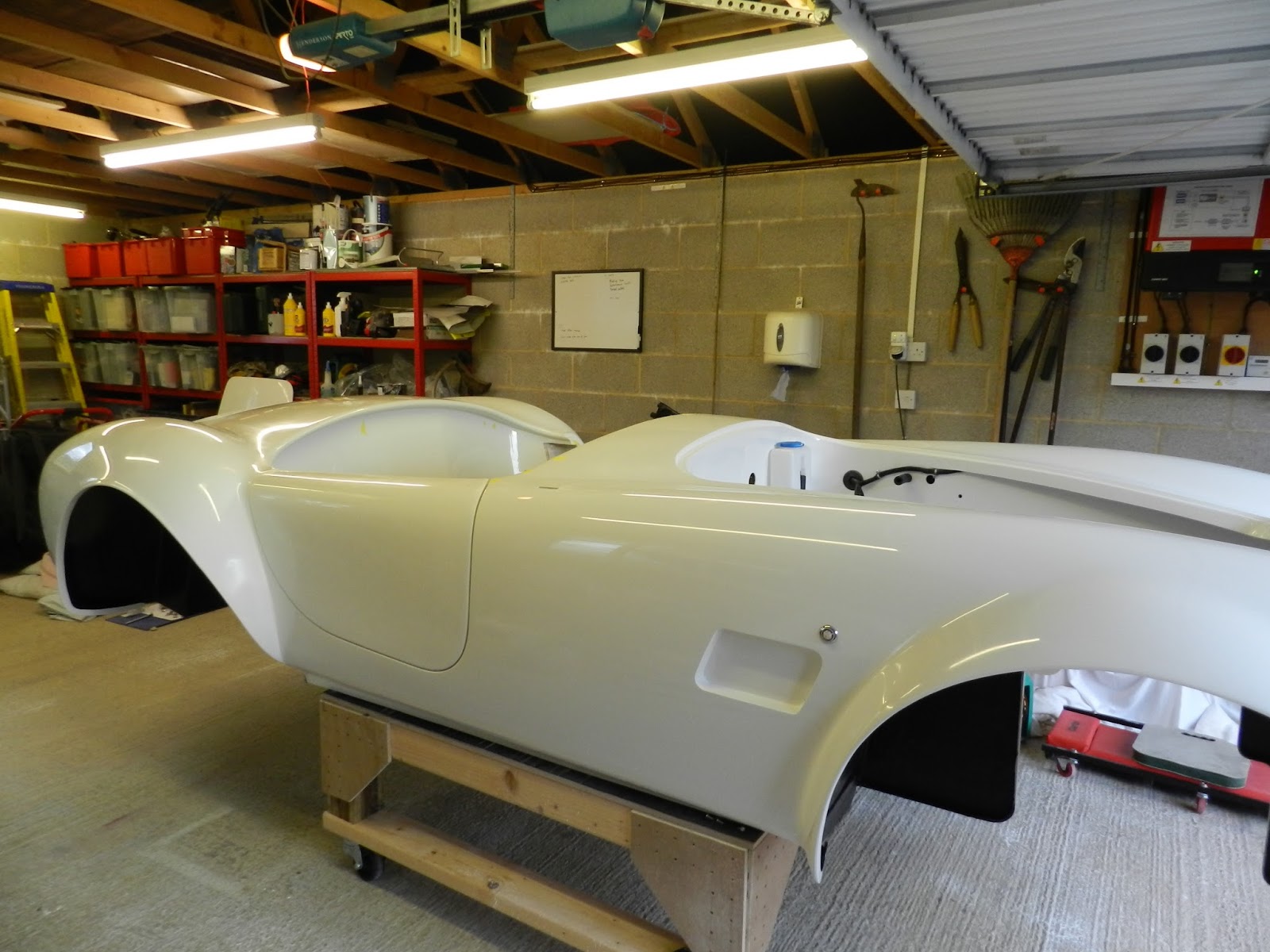 |
| Doors fitted, lined up and first polish |
Subscribe to:
Posts (Atom)