Monday, January 18, 2016

Chevy LS6 cooling and heating hoses part 1

It is so cold at the moment that I have spent nearly two days working out where the hoses and vacuum tubes go and which take off pipes on the LS6 engine need blocking off in my Cobra. Well it is better than going out in to the garage and is so much warmer!

Here is how I will connect up the numerous hoses and vacuum tubes to my LS6. 

Heater

There are the following connections:
  • 2 take-offs to the engine block on the lower offside
  • 2 take-offs to the heater on the nearside inner wing
The take offs to the heater outlets on the engine at the offside are connected using hoses running around the front of engine (under the upper brace bar/cross member) and back along the chassis rail at the nearside to the heater outlets.

I have used GD's stainless steel heater pipes to add a bit of bling! Only the front is shown in the photo below. There is another pair of pipes that fit to the nearside of the chassis.
Front stainless steel heater pipes fixed to the upper brace bar
Cooling

A short hose connects the upper outlet from the engine to the long side of the header tank. The longer hose connects the header tank to the top of the radiator. 

Another short section of hose connects the lower coolant outlet to the long stainless steel pipe. NOTE: Check that there is a thermostat in the housing, I didn't have one! Re-seal using Hylomar blue sealant if you don't want any leaks - even with the rubber seal in place! At the other end the 90 degree hose connects this pipe to the lower connection on the radiator.
Cooling hoses and header tank
The header tank is fixed to the top brace bar with button head bolts, although the hose helps hold this in place. The bracket goes around the bar. Here I used rivnuts.
Rivnuts inserted in the upper brace bar
Vacuum

Looking from the offside, there are the following connections:
  • 1 take off from mid left of plenum
  • 1 take off from top right of throttle
  • 1 take off from lower right (underneath front) of the throttle 
    Throttle body from offside
Block off the mid left take-off from the plastic plenum.

Block off the top right outlet from the throttle.

The connection to the lower right of the throttle (virtually underneath the throttle pot) is not used - no need to block this off.

Looking from the nearside there are the following connections:
  • 1 take off from mid right of the plenum
  • 1 take off from under the left of the throttle - simply connects to other side of the throttle
  • 1 take off pipe from the head (with a cross link pipe between the two heads)
Throttle body from nearside
Link the bottom right pipe from the cylinder head (with the cross link) to the lower take-off on the header tank.

Connect a hose from the higher header tank connection down to the lower part of the chassis. Clip this to the chassis.

The mid left breather on the throttle is not used. Block off this stub from the plenum.

The lower left take-off is not used. No need to block off as it just connects to the other side.

There are 2 take-offs from the rocker covers (1 on each)
Offside rocker cover

Nearside rocker cover

The offside rocker cover is connected to the air intake and a pipe also goes around the back of the engine to the nearside rocker cover vent.

There is 1 take off at the rear of the plenum which is blocked off.
Rear take off from plenum
Air intake

The long straight section of the air intake is fitted towards the engine – vacuum take off to the offside and the air sensor to the nearside. The air sensor came from Canems. This needs drilling out for a grommet. The sensor is simply pushed through this grommet (there is already an undersized hole here).

Hole in the air intake for the sensor on the near side
The stainless steel air intake outlet is connected to the offside rocker cover pipe vent at the front. Here a tee piece is inserted to take the vacuum pipe around the back of the engine to the nearside rocker cover vent (at the rear of the engine).

Fuel rail

The screw end of the fuel rail is covered with a dust cap. This acts as a fuel bleed.
Threaded end of fuel rail on nearside

Tuesday, January 12, 2016

Carpets part 1

A pile of carpet pieces arrived, with no instructions. At first I thought that I knew where each bit went, but when it came to it I didn't. When I looked at other blogs, I found that they assumed we all knew where to put the bits too.

Boot carpet

So here is my take on where all the pieces go, starting with the boot:
Side panels near lights in boot
Side panels above rear axle area in boot
Main floor piece above rear axle, fuel tank and vertical surfaces of wheel arches in boot
Rear floor area and up under boot lock striker plate
Main boot floor area
So, once I had worked that lot out, it was down to sticking in place what I could. As it turned out not much!

I put the carpet sections in place, then marked the edges in pencil. I realised that at this stage I could only fix the side panels. Contact adhesive was applied to the body in these areas and the carpet, then allowed to dry for around 10 minutes before offering up to its final place. The carpet was firmly pressed against the side, once it was in place.
Side panel above rear axle glued in place
Rear side panel glued in place
This was repeated on the other side.

Transmission tunnel carpet

Whilst this was not glued, it was fixed by the front cross-brace mounting feet. It will not be glued in place until after the body is mounted on the chassis. I had fitted rivnuts into the transmission tunnel below the cross-brace feet. I made sure that the carpet was in its correct position. Then from underneath I poked a thin screw driver through the rivnuts to make holes in the carpet. The holes were enlarged a little with a craft knife and then screws were fitted along with a few washers to pack out the carpet to bracket gap.
Carpet fixed down on transmission tunnel
The central under dash plate was fitted to the cross-braces, using M5 button heads and nyloc nuts.
Central under dash panel fitted

Monday, January 11, 2016

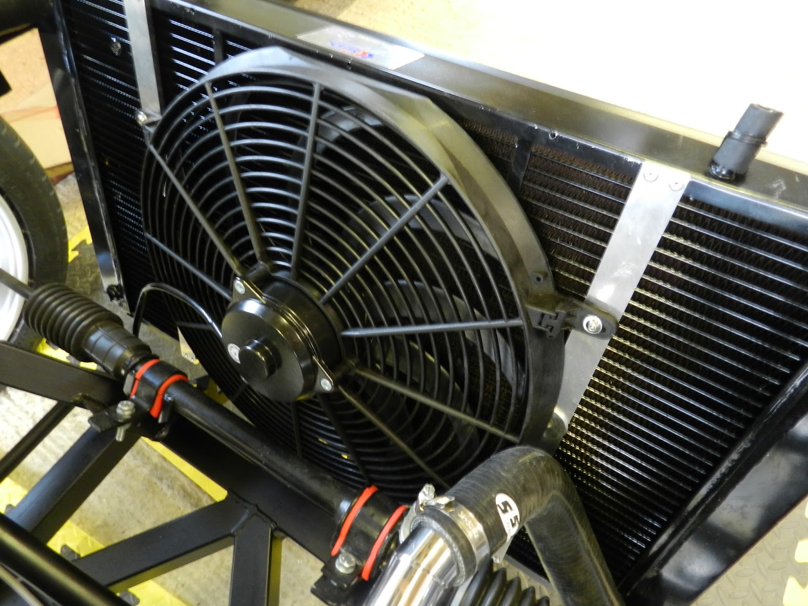
Fitting the cooling fan

The fan

I decided to fit one fan behind the radiator. Some people fit one or two fans in front of the radiator. Fitting behind (suction) appears to be more efficient and should get fewer insects bonded on to it!

I bought a 16" suction fan with curved blades that can flow around 3,400 m3/h, from Car Builder Solutions.

Mounting the fan

I pinched the fixing method from Simon (see blog link on right) and blagged some 6 mm thick x 25 mm wide flat bar aluminium from Keith Akerman!

The principle is to fix the bars to the radiator, then fix the fan to the bars.

After cutting the aluminium to the correct length, I drilled two 4 mm holes close to each end of each bar to take 14 mm long rivets.
Aluminium bars with holes drilled in ends
Next the cheek nipping bit. I marked the position of the bars and drilled the holes corresponding to the holes already drilled at the end of each bar onto the radiator frame. All the blogs said that there was no risk in hitting any of the radiator cores, even though everyone had some trepidation in drilling the holes! I made sure that the holes were near to the outside of the radiator, just to be safe, prior to drilling. The bars were loosely fixed to the radiator using pop rivets, just pushing them in place.
Radiator edge with holes drilled for bars
Next the mounting feet were attached to the fan and the holes were marked on the bars. The bars were then drilled to take the M5 rivnuts and countersunk from behind (radiator side).
Bars riveted in place after fitting rivnuts facing fan
Rivnut in mounting foot

The fan was then laid over the four rivnuts to make sure it still fit. Then the pop rivets in the end of each bar were fixed in place. Finally M5 button head screws and washers were used to secure the fan.
Fan secured to bars
Mounting the radiator assembly

The upper radiator frame was re-attached to the chassis, using two bolts. The 'fixing kit' supplied by GD consists of two small sections of rubber hose and a few nuts, washers and bolts. The radiator was located using the protruding pegs from the radiator to the top radiator frame through the rubber mounts. It was then fixed onto the lower mounts using the two nuts and bolts supplied. This results in the radiator being at an angle with the top towards the front of the car. This is a straight forward job.
Fan mounted to radiator
Radiator and fan mounted into chassis

Saturday, January 09, 2016

Fuel filler breather

Whilst I had installed the fuel filler, I hadn't put in the breather pipe. This is simply a piece of brake pipe connecting the filler to the outside world.

A 5 mm hole was drilled in the boot floor, close to the wheel arch. The pipe was fed through this hole and then bent, using a pipe bending tool and by hand, to fit around the boot side of the wheel arch and to align with the fuel filler adapter. The fuel filler adapter was then fitted, after flaring the pipe end. A tiny amount of Loctite 572 was used on the male surface to hold the small insert of the adapter in place whilst I tightened up the fixing.
Fuel filler with pipe attached by the adapter
The pipe was attached to the inner arch with black plastic P clips and self tappers. The bottom of the pipe was finished flush with the bottom of the car floor from the outside. The bottom was sealed with silicone (as the pipe is only a breather I didn't use a grommet). Carpet will cover the pipe when fitted.
Breather pipe clipped in place and sealed at the bottom

Friday, January 08, 2016

Gas strut in boot

Boot stay

After putting off the installation of the boot stay, I finally committed myself to fitting in a gas strut. I had put off fitting the supplied strut, because I didn't like the GD strut or the method of fitting. So I created my own! However, like GD I have only fitted one stay, as I felt that this was sufficient for the boot lid weight.

The method of fixing is similar to that of the bonnet on my Cobra (see earlier blog). Again I bought the stuff (including a GSV8-200 adjustable gas strut) from SGS Engineering - a top company, in my opinion, with top service.

I had also bought a triangular bracket from SGS. This had a 10 mm ball fixing in place. A second bracket was made up using 3 mm thick angle aluminium, about 150 mm long, to strengthen the lip (fitted up behind the boot lip). The tip of the triangular part (see photo) was bent slightly, so that it touched the SGS bracket when in place (to add strength).
Bracket and angle aluminium that it was cut from
Two fixing holes were marked on the lip of the boot, using the SGS bracket, with the centre of the bracket about 160mm from the back of the cockpit side opening.
Two holes in side lip, seen from rear of boot
Using these two holes, the angle bracket was marked and drilled through and temporally fitted in place. Two pilot holes were then drilled down into the recess (around the boot edge), about 70 mm apart and through into the bracket to mark the hole centres. The bracket was taken off, then the holes carefully drilled out to size - I used M5 fixings. The two brackets were bolted in place, using button heads plus nyloc nuts. Edit: Forgot to mention that the two brackets were bolted together.
Two fixings in recess of boot lid surround
Bracket bolted in place, two bolts were also inserted in the recess behind the black sealing strip
Now I turned my attention to the boot lid fixing. Another SGS bracket was used here, also with a captive 10 mm ball stud. First the bracket was bent to the curve of the boot lid rib, before fixing in place using countersunk rivnuts and button heads. The open gas strut was used to find the location of the bracket
Bracket bent to curve of boot lid
Next I fitted the gas strut to the two ball studs, with the large diameter part of the strut attached to the boot lid (this will be lower than the other fixing point most of the time). Like the bonnet, the boot gas strut instructions recommend letting gas out in one second bursts. In my enthusiasm, I let out a little too much gas at around 19 seconds, so I will need to get it re-gassed! I had a spare locking mechanism from the bonnet attempt, so I used this as there was adequate clearance here.
Gas strut in place with locking mechanism
Looks a bit better than the GD strut and should be a little less rattly.

Hello and get well to Malcolm!

A friend of mine in Horsham is not feeling too well at the moment. We meet up a couple of times a year with him and wife Lin. We originally met in the South of France over 25 years ago, when we both had Citroens. Malcolm has driven my Caterham and I know he wants a go in the Cobra when it is complete, so I look forward to that blast in the 'beast', as he calls it! I know he looks at this blog on his big internet enabled tv.

Monday, January 04, 2016

Small but important jobs

Loads of small jobs to do. Feels great to knock them off the list!

Coil packs

Re-fitted the plug leads and coil packs today. I have fixed the brackets to the rocker covers using M6 16 mm button head screws. The holes in the rocker covers that were not used had M6 12 mm button heads inserted to finish them off.
Coils and plug leads fitted
Exhaust clamps

I was not happy with the front and middle exhaust clamps. They hung down too low and so would reduce ground clearance and the exposed threads were an invitation to make contact with the road. Even if I twisted them around, I couldn't gain much ground clearance without coming into contact with the chassis. As we have quite high speed bumps on our road (higher than the legal limit of 4"), I needed to make sure that the ground clearance was as high as possible.
Standard brackets hang down too far
I bought four Mikalor exhaust clamps from Westfield Fasteners to replace the standard clamps. Not cheap at £18 plus p&p, but worth the outlay. The photo above shows the before view and below shows the after views.
Almost flat clamps (Mikalor)
Front clamps fitted
Gearbox mount bolts

Replaced the two bolts gearbox mount bolts with 10.9 grade bolts. The others had lost there edge from being put in, thread locked and taken out a few times.
New gearbox mount bolts
Brace bars and cooling

I refitted the front brace bars, the radiator support frame and the radiator. This should have been really easy, but for some reason the bolts took some inserting in the brace bars, before fixing with nyloc nuts.
Brace bars, radiator support frame and radiator in place
Once the radiator support frame was in place, I trial fitted the header tank and hoses. This was an easy job and very intuitive. I have used black silicone hoses with W4 clamps (stainless steel). I replaced the supplied air intake zinc plated clamps with four 100 mm W4 clamps. The radiator will have to come off for the fan to be fitted.
Hoses and header tank trial fitted
Idler pulley

The idler pulley is not used on the GD, so I removed the bracket and pulley.
Idler pulley on right
Idler pulley removed
Transmission tunnel cover

The transmission tunnel cover needed a hole cutting out for the gear shifter. First I marked this out by measuring the position of the shifter, then drawing a circle 65 mm in diameter. My chassis is a Euro, so the sponge rubber was in place, therefore the hole was cut from the bottom side of the panel.

Put away the Dremel for this job. I broke a cutting bit. The hole was cut out using a jig saw and then tidied up with a half round file.
Hole cut in transmission tunnel cover
Clutch hydraulics

A smear of Loctite 572 was applied to the clutch pipe connectors (there are four surfaces to be treated) before they were connected to the block. The block was dismantled to allow the pipe connectors to be nipped up. The rigid brake pipes from the chassis were already in place.
From left to right clutch bleed, clutch feed, brake pipes x 2 
The two braided clutch pipes were strapped together with a couple of plastic tie wraps.

So a load of easy/small jobs done and out of the way.

Friday, January 01, 2016

Cobra exhaust

New Year's day (happy 2016 to all readers) and another few hours in the garage to tackle the exhaust system.

I laid out the various parts of the exhaust system so that I knew where to fix them. The system consists of various tubes, catalytic converters, a balance box on the central pipes, plus two Cherry Bomb silencers. I have already fitted the headers. The Cherry Bombs (silencers!!) will be fitted later, once the body is in place. The diameter of the Cherry Bombs is so big that I could almost park the every day car in them!
Exhaust system, less headers, laid out
What I realised after initially assembling the system on the chassis was that the gearbox mounting plate, which also acts as a point from which to support the exhaust system on my car, had been mounted (note how I don't take any blame here) on top of the chassis lugs (logical place?). However, it should have been mounted below to avoid the pipes touching the chassis - not the best engineering solution I have seen, but the four high tensile bolts should be fine as the weight of the gearbox tail and the exhaust system are not massive. Nothing about this location in the manual, so it was trial and error, mainly the latter.
Gearbox mounting plate above the lugs
Also, I had to open up the exhaust mounting hole a little to fit the threaded part of the bobbin from which the exhaust system is supported. So the mounting plate was removed yet again and bolted to the chassis from the underside. This time it was a little more difficult to get out, as the exhaust pipes were in the way! 
Gearbox mounting plate moved to below the chassis
By moving the bracket to the underside of the chassis it moved the exhaust mount about 12 - 15 mm lower, so giving clearance to the chassis. Heat Resistant silicone was applied to the system where the pipes joined to reduce any risk of blowing (hopefully).

The rear of the exhaust system was located using reinforced rubber and six bolts (as supplied by GD), three bolts (with shake proof washers) locate into the rivnuts in the chassis and three bolts go through the bracket and the rubber mount, secured by nyloc nuts. The rubber mount needed trimming to size and holes drilling.
Rear view of exhaust before rubber mount fitted
The bracket supplied keeps the pipes the correct distance apart and helps to locate them. This is only fitted hand tight, so was not supposed to be in the right location as supplied. Drilling the rubber is interesting. It seems to self-heal after drilling!
Rear exhaust mount fitted, the six fixings can be seen
Now all the clamps were tightened up to secure the system in place and the oxygen (lambda) sensors were fitted into each side below the headers. These will be wired in later.
Exhaust clamps below a header and with the lambda sensor fitted