Monday, August 15, 2016

Cutting back the Cobra wheel arches

I had a look at Keith Akerman's finished car (if ever a Cobra is finished) on Sunday and it reminded me that I needed to trim back the wheel arch return. I have seen a photo of the result if you do not - cringe £££££!

The tyre needs to clear the wheel arch at full lock, with the suspension compressed. This is achieved by moving the suspension up, so that the mountings holes for the shockers are 10" (250 mm) apart. This is the maximum compression of the suspension. To achieve this I removed the shocker.
Shocker removed to measure the maximum compression
By cutting back the wheel arch return, it avoids the tyre ever contacting the body .... in theory at least.
So out with the trusty Dremel and marker pen.
Line to cut back on wheel arch return
The return was cut with the Dremel, then a sanding drum and finally rubbed down by hand using P400 paper.
Finished job
This was a long job and very dusty, so a mask was used to avoid breathing in the GRP dust. But it was worth the effort.

Saturday, August 13, 2016

Cobra mirrors

Got a while in the garage today. A bit unexpected, but great to be building again. So I decided to fix the mirrors. I needed to do this so that I could show where the mirrors were for a car cover.

External mirrors

The mirrors come with inappropriate mountings, so after carefully removing the glass, the fixings were removed by unscrewing the mirror body from the ball joint on the fixing.
Mirrors as supplied
Standard fixing replaced with GD arm
This is simply a screw in to the ball joint. The mirror is then replaced and  hey presto, you have a mirror suitable for the Cobra.

First I removed the screen, by undoing the four screws at each side on the stanchions and the centre stay fixing.

Next I applied some masking tape to the outside edges of the stanchions - from the second screw down to below the third screw. Then I marked a centre line for each of the stanchions on the masking tape. The lower screw hole for the mirrors were 160mm up from the stanchion escutcheon, so a mark was made at this point.
Tape marked with centre line and hole positions
I then used some scrap aluminium to protect the chrome on the stanchions, with holes drilled oversize and approximately in the right places in one piece.
Scrap alli held in place with clamps
A 3mm pilot hole was drilled through each stanchion, before opening up to 4.5mm. Each hole was then tapped to take the M5 bolt supplied.
Hands free tapping!
Then the second hole was marked, drilled and tapped in each stanchion. Two M5 screws were then used to fix each mirror to the stanchions. Done!
Both mirrors in place
As my garage is not complete yet, I couldn't shorten the screws that hold the arms or flatten the head of the third screw on each stanchion. These need to be done to avoid damaging the windscreen when the screws are inserted and tightened in to the holes and to allow the mirror arm fitting to sit flush with the stanchion. I will do this when my bench and grinder are in place.

Internal rear view mirror

This is simply clamped to the central windscreen stay.
Here you can see the location bracket of the internal rear view mirror. The black rubber edging is for the IVA.

Thursday, August 11, 2016

Cobra emerges from the boxes!

We are now in the new house!

The part built Cobra stayed at the old house for three weeks, before we took possession of the new house (and garage).  I brought the car to the new house a few days after we moved in, using a car trailer borrowed from my friend Mike. There was just enough room for it in the garage amongst the boxes and junk. The Cobra was certainly a good talking point with the new neighbours - a great way to get to know people.

Once the stuff was cleared up and some of it thrown out, it started to look more like a garage than a tip. I have put up some Storewall (wall storage, what else?), to get things out of the way and off the floor. I had almost forgotten how good the car looked until it emerged from the boxes!
The Cobra in it's new home
We have been here nearly four weeks now and the garage is finally getting organised. Cabinets, floor tiles and a work bench are being fitted next week, so there will be no excuses after that to get on with the remainder of the build.

Monday, July 25, 2016

Saturday, June 18, 2016

House move stops play!

Sorry to say that our house move has stopped work on the Cobra build.
Boxes everywhere!
Not only does the house move interfere with the build, but we will be without a house and hence a garage during this process. So we are out of our house with nowhere, apart from the caravan, to move in to from next week!

The Cobra will stay at our old house/garage, at least for a while, thanks to a generous offer from Jayne, our buyer. So the build will grind to a halt for the next few weeks, while the lawyers do their stuff. Hopefully it won't be too long.

Apologies for the break in activity. Normal service will be resumed as soon as possible!

Monday, June 06, 2016

Under tray fixing

The under tray is made of aluminium sheet and fits beneath the radiator and into the lower area of the nose.

I had to make sure that the tray avoided the 'oil cooler air intake'. It locates below this intake on the inside of the nose and is fixed to the lower radiator mounting points. It should be a tight push fit. Two holes were marked on the under tray and drilled to allow the lower radiator mounting bolts to be used. The holes had to be slotted a little to allow the bolts to be fitted. What a faffy job to get the bolts back in place, as my radiator and the mounting holes do not line up perfectly!
Radiator fixing bolts used to secure under tray
Next the two side fixing brackets (bent pieces of aluminium) were marked and four holes drilled in each to take 5mm button head bolts with nylocs. The holes were drilled in the brackets so that two went through to the tray and two through the inner wing. Because I did not want to remove the radiator bolts again, the drilling was an awkward job and required the 90 degree drill attachment, but now it is done I am happy with it.
Bracket used to fix under tray with button head bolts

Saturday, June 04, 2016

Steering column

I had the steering column in my boxes, so I thought it was about time I put it on the car.

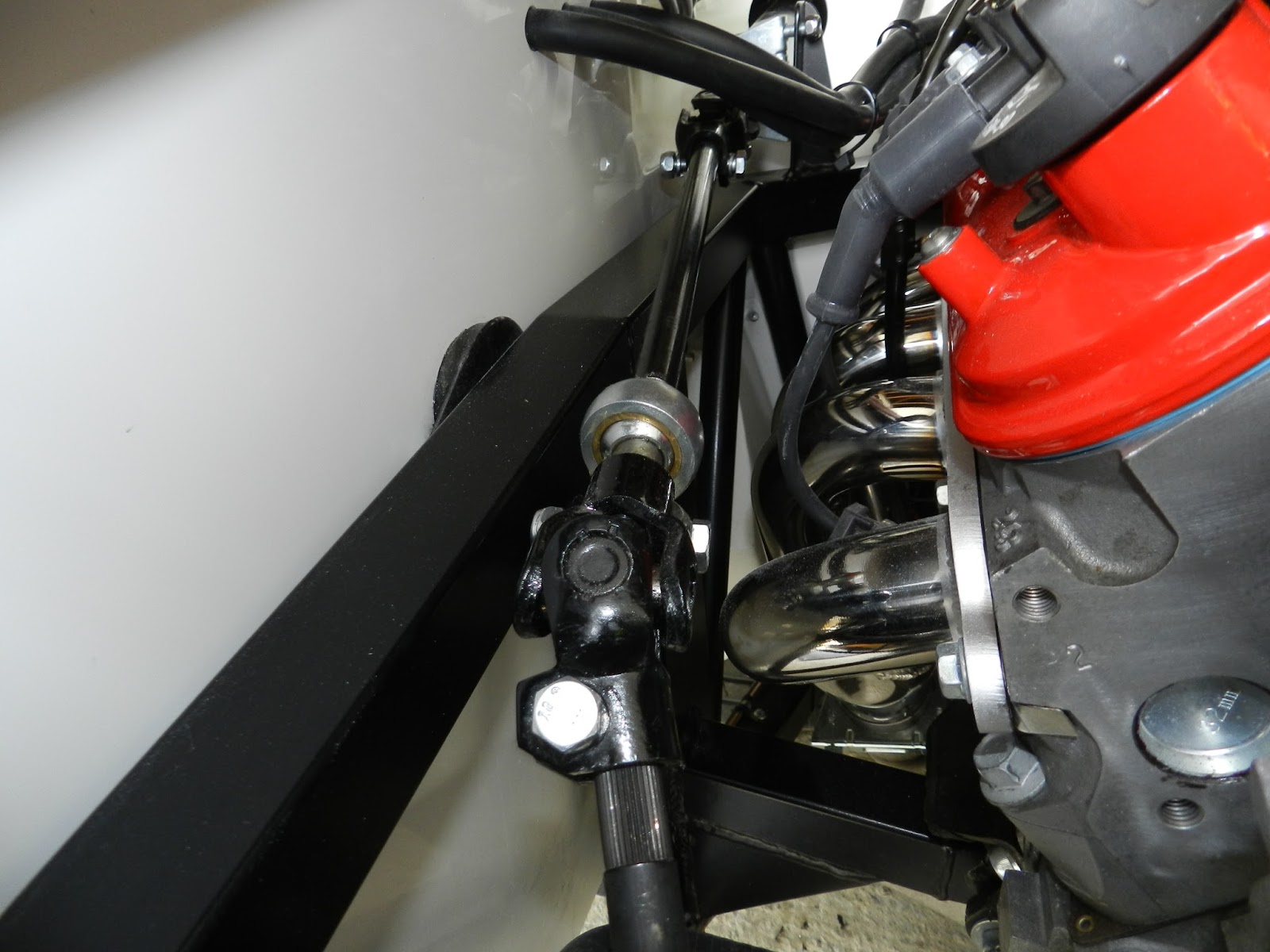
There are three parts to the column. The lower section that connects to the rack. The middle section, with the rose joint and the upper Vectra section with the rake adjustment, collapsible mechanism and the electrical connections. At this stage all were fitted just hand tight with the nylocs, bolts and washers supplied

First I fitted the lower section. This was simply a case of removing the nut and bolt from the joint, then sliding over the rack splines and re-fitting the nut and bolt. This was required at each joint.
Connecting the lower section to the rack
Next, the middle section rose joint was packed with grease and connected to the lower section. The threaded part of the rose joint was mounted on the chassis bracket. NOTE: See IVA and Post IVA category in the Build Process.
Middle section connected to lower shaft. Rose joint can be seen here.
Finally, I fed the upper section through the bulkhead and the locating U-clamp from the passenger compartment and connected this to the middle section. Not forgetting to put the bulkhead grommet in place. Here I had to file the bolt cut out groove on the upper column shaft a little to accommodate the bolt, as the Vectra column has a smaller groove than required. A round file did the trick here.
Upper column connected to middle section.
Now I found that the column in the drivers compartment stuck out a little too far, so I could not fit the mounting bolts. This was even with the bolts hand tight in the joints. I suspect that it is simply a case to tapping the steering wheel end of the column to move the inner shaft in to the column assembly, but better check first. Advice has now been requested from Andy at GD!

Once the nuts and bolts are tightened up, I will need to make sure that there are no tight spots when turning the steering wheel. If there are the joints will need moving around the splines.