Attaching gearbox to engine
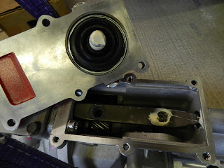
The hydraulic pipes were attached to the release bearing (see photo below), using a small amount of Loctite 572 on to the tapered surface, making sure not to get any in the pipes. Do not apply top the thread.
The end of the gearbox output shaft was lubricated with a little grease. Using the engine hoist and a couple of slings, the gearbox and bell housing were offered up to the engine.
The end of the gearbox output shaft was lubricated with a little grease. Using the engine hoist and a couple of slings, the gearbox and bell housing were offered up to the engine.
 |
| Engine and gearbox being aligned |
The shaft went through the clutch plate and entered the spigot bearing. Making sure that the shaft was lined up, the bell housing was then twisted a little and pushed home over the locating pegs. The bell housing was then bolted up to the engine block using high tensile bolts and torqued to 37 ft lb. Thread lock was applied to these bolts before tightening.
Gearbox mount
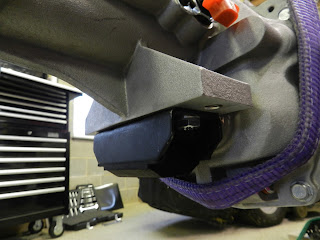
The gearbox mounting was fixed to the gearbox tail with two high tensile bolts and thread lock used.
Gearbox mount in place
|
After painting the mounting bracket with POR 15, it was loosely fitted to the chassis with high tensile bolts and nyloc nuts. This allows a small amount of movement in order to line up the gearbox mounting bolts with the plate.
After fitting the gearbox, bell housing and the engine together, it was time to put the unit in to the chassis.
Fitting the unit in to the chassis
To get the unit in easier, I took off the radiator support frame and the two removable cross member from the front of the chassis (the top brace and the diagonal).
 |
| Removable cross brace (top right) and diagonal brace |
 |
| Radiator support frame and cross-braces removed from front of chassis |
 |
| Gear shifter removed |
Two slings were attached to the hoist after feeding them under the engine and bell housing. I couldn't have done this task on my own, not enough hands!
Using the hoist and gently moving the chassis, we manoeuvred the assembly in to place. A careful stepped motion (i.e. lower, push in, lower etc) was used on the hoist to get the assembly into the chassis. The LS6 engine has the batwing sump and this went under the engine mounts on the chassis. The prop shaft was inserted in to the tail of the gearbox, lubricating the gearbox seal with the gearbox oil.
 |
| Engine and gearbox unit on the hoist |
 |
| Matthew aligning the prop shaft |
The four bolts and nuts were used to secure the gearbox mounting bracket, after elongating the two mount holes. The two high tensile bolts were then used to secure the gearbox mount to the bracket.
All the bolts were finally tightened once the assembly was in place.
 |
| Engine fully fitted |
 |
| Another view of the engine and gearbox in place |
So now I have some space in the garage, after moving the engine, bell housing and gearbox.


No comments:
Post a Comment