IVA test
I was contacted by DVSA yesterday to say that some of my photos looked to have been taken in a warehouse or factory, so would I confirm that only me or friends had built the car and that this 'lack' of information would delay my application. The photos in question were of me collecting the body in a van and the chassis being strapped on to a trailer outside Gardner Douglas. In addition I had already sent a signed declaration that I had built the car myself as an amateur builder. This blog also confirms that.
In my response to DVSA, I bit my lip and did not put what I really thought of them!
This morning I had another two emails. I tentatively opened them, expecting even more daft questions. But no, one was confirmation of payment of the fee (£450). The second said that the application had been assessed and had now been passed to the test centre to book the test appointment.
Another step in the IVA minefield.
Leaks
The leaks from the clutch reservoir and coolant from the thermostat housing appear to have been cured. Also no leak from the clutch master cylinder in the compartment behind the wheel. Yippee!

Dale's Gardner Douglas 427 mk4 Building an AC Cobra re-creation
Friday, January 13, 2017

Thursday, January 12, 2017
Small things
It has been snowing on and off today and is very cold in the garage, so time in there was kept to a minimum!
Speedometer
After using the wrong diff ratio the first time, I recalculated the speedo setting with the correct ratio at 27,868 for the ETB gauge. This will need putting in to the speedo prior to using the car.
Front dummy number plate
After spraying the dummy number plate satin black, I fitted it to the car using 19mm P-clips and button head bolts.
Clutch reservoir
I noticed a fluid weep from the reservoir, so had to remove it and refit. Looks like it is cured.
Coolant
Following my abortive attempt at filling the cooling system, I had to drain the fluid because of a leak at the thermostat housing.
I rescued the fluid, so that I could re-use it! The thermostat housing leak was sealed with Hylomar sealant and then refitted to the engine and the hoses. Care was needed not to trap the thermostat between the housing and the outlet, otherwise it couldn't be sealed (as I found out!).
Speedometer
After using the wrong diff ratio the first time, I recalculated the speedo setting with the correct ratio at 27,868 for the ETB gauge. This will need putting in to the speedo prior to using the car.
Front dummy number plate
After spraying the dummy number plate satin black, I fitted it to the car using 19mm P-clips and button head bolts.
 |
| Dummy number plate can be seen here |
I noticed a fluid weep from the reservoir, so had to remove it and refit. Looks like it is cured.
Coolant
Following my abortive attempt at filling the cooling system, I had to drain the fluid because of a leak at the thermostat housing.
 |
| Leak under thermostat housing on right of photo |
 |
| Reseated and sealed |
Tuesday, January 10, 2017
Coolant, clutch, IVA, ECU etc
Coolant
The coolant system took around 16 ltrs, 70% water to 30% antifreeze. This was added to the stainless steel expansion tank at the front of the engine compartment.
It was poured in gradually to reduce the risk of air locks. All pipes were checked for leaks at this stage. There was a leak in the thermostat housing - mutter, mutter. As this had a rubber O-ring I had not used any sealant. I should have - another lesson! So that's a drain down tomorrow. Not difficult, but a job I could do without.
If you are doing yours, remember that I have a Chevy LS6 engine. The amounts may differ on other engine types.
Clutch fluid
The reservoir was filled with DOT4 fluid. An auto bleed system was used, so that I could do it on my own. Air pressure from one of the tyres was used.
Oh, and I noticed that a wire had broken to the knock sensor, so I had to repair this.
ECU
The ECU was fitted to the centre under dash tray using button head bolts in to rivnuts. I made sure that there would be clearance for the gauges and that the connector would fit the ECU in that position.
The remote button for the speedo was fitted to the central tray too. It is concealed, but can be operated from the driver's seat. There is a gap between the underside of the tray and the transmission tunnel top.
NOTE: Fit a PC flylead to the ECU to make access to the ECU easier. See IVA and Post IVA category in the Build Process.
Tachometer
The dip switches on the back were checked to make sure that the settings were correct. For the ETB tacho the first 3 switches are set to 1 (on) and the remainder are set to 0 (off) for the LSV8.
The speedo will need setting too, but for the first calculation I had used the 3.23 diff and the later chassis (including mine) have a 3.07 diff. So I need to re-check the setting with ETB.
The faulty switch for the rear fog light was replaced whilst I played with the dashboard.
Starter heat shield
I had left this off for some reason. So it was added. Needed to remove the dip stick first.
IVA items
A dummy number plate is needed for the IVA and was made from MDF, sprayed black and fixed to the bar at the front in the nose using two 19mm P-clips.
The rear number plate lamp had the bolt changed for a button head to comply with the 5mm radius rule.
The coolant system took around 16 ltrs, 70% water to 30% antifreeze. This was added to the stainless steel expansion tank at the front of the engine compartment.
 |
| Coolant header tank |
If you are doing yours, remember that I have a Chevy LS6 engine. The amounts may differ on other engine types.
Clutch fluid
The reservoir was filled with DOT4 fluid. An auto bleed system was used, so that I could do it on my own. Air pressure from one of the tyres was used.
 |
| Clutch reservoir. Bleed nipple is on right of two pipes - not easy to get at |
ECU
The ECU was fitted to the centre under dash tray using button head bolts in to rivnuts. I made sure that there would be clearance for the gauges and that the connector would fit the ECU in that position.
 |
| ECU bolted to centre tray |
NOTE: Fit a PC flylead to the ECU to make access to the ECU easier. See IVA and Post IVA category in the Build Process.
Tachometer
The dip switches on the back were checked to make sure that the settings were correct. For the ETB tacho the first 3 switches are set to 1 (on) and the remainder are set to 0 (off) for the LSV8.
The speedo will need setting too, but for the first calculation I had used the 3.23 diff and the later chassis (including mine) have a 3.07 diff. So I need to re-check the setting with ETB.
The faulty switch for the rear fog light was replaced whilst I played with the dashboard.
Starter heat shield
I had left this off for some reason. So it was added. Needed to remove the dip stick first.
IVA items
A dummy number plate is needed for the IVA and was made from MDF, sprayed black and fixed to the bar at the front in the nose using two 19mm P-clips.
The rear number plate lamp had the bolt changed for a button head to comply with the 5mm radius rule.
 |
| Hexagonal bolt swapped for button head |
Sunday, January 08, 2017
Dashboard and electrical - testing
I put the ignition barrel back in. Click the U clip down using a thin screw driver.
If the key is in the same position as it was when it came out it should click back in place. If it does not go in it could either be that the U shaped clip has not been pushed down fully or the key has moved a little in the barrel. The first issue needs the U clip pushing down until it clicks (Tip: use your phone camera to see this). If the clip is fully down then it could be that the key has moved. The key can be moved carefully anti clockwise (when viewed from the back) to the stop or clockwise, but whatever you do don't let the pin go as far as the hole at the end (look at the side opposite the key to see this)! The barrel should go fully home and click in to place.
At this stage the fuel pump was not connected to avoid any risk of starting up the engine by mistake. Not all the electrics can be tested yet e.g. engine related items cannot.
The results of the first test were:
Working okay
Heater blower - off, speed 1, speed 2
Hazard warning lights - all four indicators flash (should lights on wings flash too?)
Hazard warning dash light
Indicator warning lights - when hazards flash
Brake lights
Horn - initially sucked instead of blowing and produced a weasy noise. Swapped the wires around and oh boy what a noise!
Wipers - parking correct way, intermittent, speed 1, speed 2
Washers - water jet plus single wipe and park. Adjusted the aim of the jets
Rear reversing light - ignition key needs to be in fully turned position and reverse gear selected
Rear fog light - main lights need to be on - faulty switch, so this needs replacing (worked if jiggled), also I had connected the red/yellow wire by mistake (this is the reversing light wire)
Fog warning light on dash - but see above
Lights - side lights, dip, main beam
Number plate light - on with lights
Auxiliary output - on with ignition switch
Instruments (just the back lighting) - oil pressure, water temp, speedometer
Battery light - no alternator working
Brake fluid low warning - no fluid in reservoir
Not working
Instruments (just the back lighting) - fuel, voltmeter, tachometer
Lights - flash and door courtesy lights
Indicators - front, rear, side repeaters - off side front and rear work when the ignition is on, no matter what position the indicator stalk is in!
Checked the connections to the left column switch (indicators) and they are correct. Traced the wiring for the indicators in the loom and that looks okay too. The wiring to the instruments looks correct as well. So I am flummoxed.
Mark Turnbull suggested that I test the switch as this seems to be a likely cause. If this doesn't work, then it is time to call in the experts!
NOTE: The earth connections to the instruments etc have been the main problem, so pay particular attention to these.
 |
| Push this clip DOWN until it clicks |
At this stage the fuel pump was not connected to avoid any risk of starting up the engine by mistake. Not all the electrics can be tested yet e.g. engine related items cannot.
The results of the first test were:
Working okay
Heater blower - off, speed 1, speed 2
Hazard warning lights - all four indicators flash (should lights on wings flash too?)
Hazard warning dash light
Indicator warning lights - when hazards flash
Brake lights
Horn - initially sucked instead of blowing and produced a weasy noise. Swapped the wires around and oh boy what a noise!
Wipers - parking correct way, intermittent, speed 1, speed 2
Washers - water jet plus single wipe and park. Adjusted the aim of the jets
Rear reversing light - ignition key needs to be in fully turned position and reverse gear selected
Rear fog light - main lights need to be on - faulty switch, so this needs replacing (worked if jiggled), also I had connected the red/yellow wire by mistake (this is the reversing light wire)
Fog warning light on dash - but see above
Lights - side lights, dip, main beam
Number plate light - on with lights
Auxiliary output - on with ignition switch
Instruments (just the back lighting) - oil pressure, water temp, speedometer
Battery light - no alternator working
Brake fluid low warning - no fluid in reservoir
Not working
Instruments (just the back lighting) - fuel, voltmeter, tachometer
Lights - flash and door courtesy lights
Indicators - front, rear, side repeaters - off side front and rear work when the ignition is on, no matter what position the indicator stalk is in!
Checked the connections to the left column switch (indicators) and they are correct. Traced the wiring for the indicators in the loom and that looks okay too. The wiring to the instruments looks correct as well. So I am flummoxed.
Mark Turnbull suggested that I test the switch as this seems to be a likely cause. If this doesn't work, then it is time to call in the experts!
NOTE: The earth connections to the instruments etc have been the main problem, so pay particular attention to these.
Saturday, January 07, 2017
IVA application
Spent the afternoon completing the IVA (Individual Vehicle Approval) documents - amateur build declaration, application form, copy of major item invoices (chassis, body, engine, gearbox, instruments, tyres) and photos proving that I built it!
Submitted it on-line, attaching the forms and proofs.
So I am committed now to get it ready for the test by Valentine's Day. Fingers etc. crossed.
The car will go to GD for a once over, before being presented for the test in Nottingham. Paul Bowden will collect the car and transport to and from GD - saves me hiring a trailer, petrol and wear 'n tear.
Submitted it on-line, attaching the forms and proofs.
So I am committed now to get it ready for the test by Valentine's Day. Fingers etc. crossed.
The car will go to GD for a once over, before being presented for the test in Nottingham. Paul Bowden will collect the car and transport to and from GD - saves me hiring a trailer, petrol and wear 'n tear.
Friday, January 06, 2017
Electrical connections
Loom changes
Horn
These should ideally have been made before the loom was put in to the body, as it would have been much easier. On the column wiper and horn switch, there are a couple of changes to make.
First the horn relay (the third in) needs the purple loop removing.
The washer needs the green (or light green in my case) removing and replacing with an earth.
Intermittent wiper
Then its the intermittent wiper. This needs more wires changing and a relay adding (VW 3BO955531 or 357955531). This has been ordered. It was easy enough to wire, although I did not have the correct colour wires, so used the correct gauge wire that I had and marked it up with the correct colour and the relay terminal. Refer to the GD diagram for wiring.
Other connections
Now the bits that I hadn't done earlier!
The brake fluid warning wires on the loom had not been fed through the bulkhead or connected, so that was done.
Then it was pushing the fuel pump wire through the grommet at the top of the passenger foot well. Some Vaseline helped here. A new terminal has been ordered.
So hopefully that is the end of the wiring, assuming it all works! Now it is down to testing all the electrics.
Passenger seat
This was really easy compared to the driver's side. Basically I used the same process as on the drivers side, but did not have to worry about the handbrake. The seat belts were also added. Another job done.

Horn
These should ideally have been made before the loom was put in to the body, as it would have been much easier. On the column wiper and horn switch, there are a couple of changes to make.
First the horn relay (the third in) needs the purple loop removing.
 |
| Loop to remove can be seen here if you look carefully! |
 |
| Loop removed |
 |
| Earth added (see arrow) |
Washer
The washer needs the green (or light green in my case) removing and replacing with an earth.
 |
| Earth wire (black) replaced green wire |
Then its the intermittent wiper. This needs more wires changing and a relay adding (VW 3BO955531 or 357955531). This has been ordered. It was easy enough to wire, although I did not have the correct colour wires, so used the correct gauge wire that I had and marked it up with the correct colour and the relay terminal. Refer to the GD diagram for wiring.
 |
| Changes made to wiring on column switch |
Now the bits that I hadn't done earlier!
The brake fluid warning wires on the loom had not been fed through the bulkhead or connected, so that was done.
 |
| brake fluid warning wires finally connected |
So hopefully that is the end of the wiring, assuming it all works! Now it is down to testing all the electrics.
Passenger seat
This was really easy compared to the driver's side. Basically I used the same process as on the drivers side, but did not have to worry about the handbrake. The seat belts were also added. Another job done.

Wednesday, January 04, 2017
Foot well carpet and bits
Number plate lamp
Sorted the number plate light today. The bolt was not holding the chrome trim properly. I drilled out the supposedly threaded hole and fixed a rivnut. This sorted it out.
Fog light wiring
For some reason I had not connected the three wires to the loom. Straight forward.
Foot well carpet securing tags
These tags are to stop the carpet moving. This is especially important on the driver's side. The fittings are made up of a press stud for the floor and two rings for the carpet.
One of the rings had three prongs (upper), the other has holes for the prongs to go through (under carpet). First I fixed the press stud parts to the floor using self tappers. I made sure that the studs were under the carpet and not the rubber heel pad.
Chalk was applied to the top of the press studs and transferred to the back of the carpet. The ring with the holes was placed on the underside of the carpet, over the chalk mark of the press stud. The ring with the prongs on the top side was lined up with the holes and the three prongs pushed through the carpet. The prongs were then tapped over the lower ring, trapping the carpet.
So the foot well carpets are now fixed down with the press studs.
Door card
I had never been happy with the passenger door card fitting. So I took the opportunity to refit it in the right location. It was only a few millimeters out, but I could see it.
Sorted the number plate light today. The bolt was not holding the chrome trim properly. I drilled out the supposedly threaded hole and fixed a rivnut. This sorted it out.
 |
| Rear number plate light fitting with rivnut |
Fog light wiring
For some reason I had not connected the three wires to the loom. Straight forward.
Foot well carpet securing tags
These tags are to stop the carpet moving. This is especially important on the driver's side. The fittings are made up of a press stud for the floor and two rings for the carpet.
 |
| The three parts to each fitting |
 |
| Press stud on floor |
 |
| Ring on underside of carpet |
 |
| Top pronged ring can be seen here - rubbing the carpet makes the ring almost disappear |
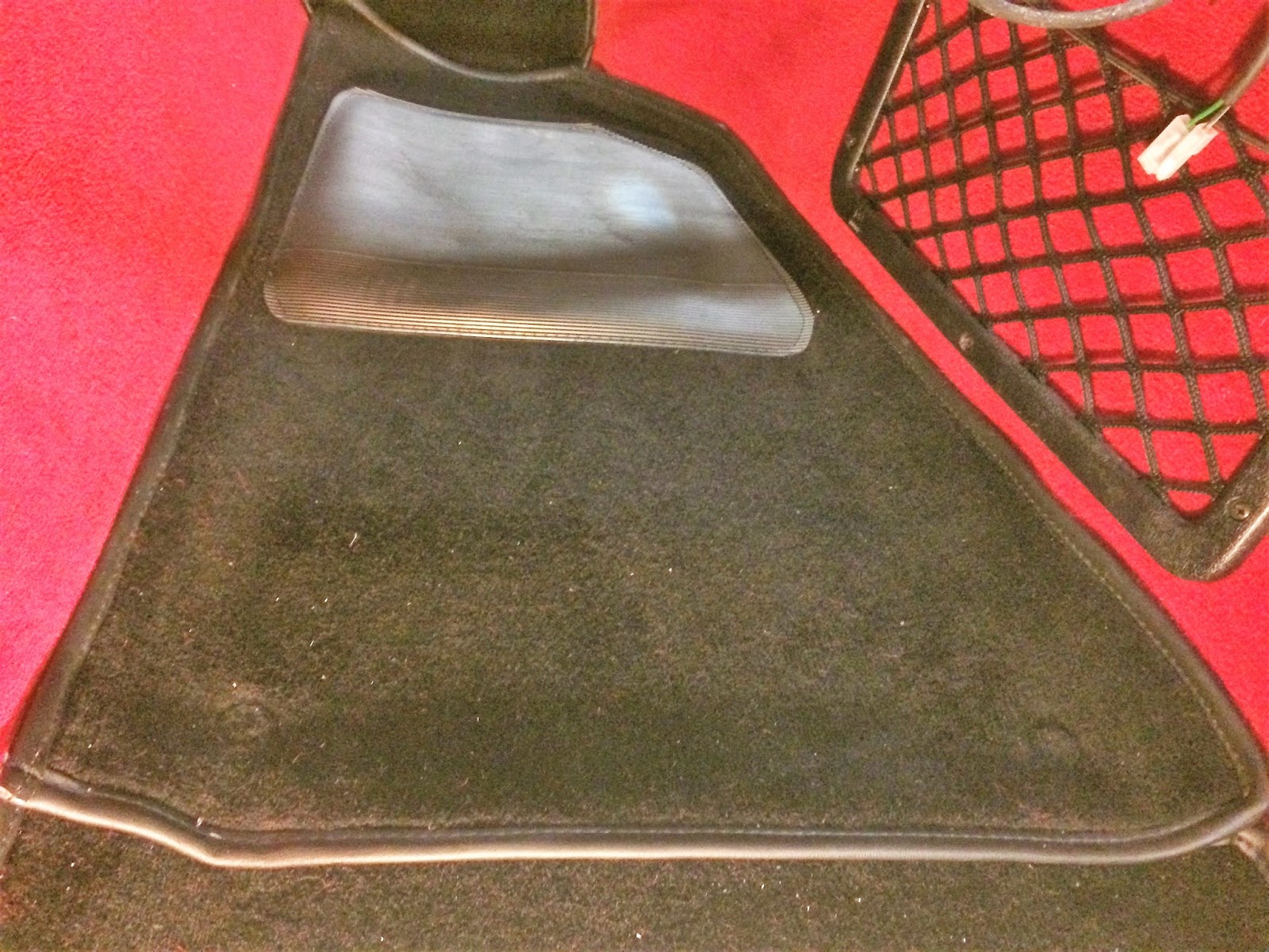 |
| Passenger foot well carpet fixed |
I had never been happy with the passenger door card fitting. So I took the opportunity to refit it in the right location. It was only a few millimeters out, but I could see it.
Subscribe to:
Posts (Atom)