
Dale's Gardner Douglas 427 mk4 Building an AC Cobra re-creation
Monday, July 25, 2016
How the Chevy LS engine is made
Here is a link to a video that shows how the LS engine is built. http://www.powernationtv.com/post/how-the-ls7-and-lt4-are-made
Saturday, June 18, 2016
House move stops play!
Sorry to say that our house move has stopped work on the Cobra build.
Not only does the house move interfere with the build, but we will be without a house and hence a garage during this process. So we are out of our house with nowhere, apart from the caravan, to move in to from next week!
The Cobra will stay at our old house/garage, at least for a while, thanks to a generous offer from Jayne, our buyer. So the build will grind to a halt for the next few weeks, while the lawyers do their stuff. Hopefully it won't be too long.
Apologies for the break in activity. Normal service will be resumed as soon as possible!
 |
| Boxes everywhere! |
The Cobra will stay at our old house/garage, at least for a while, thanks to a generous offer from Jayne, our buyer. So the build will grind to a halt for the next few weeks, while the lawyers do their stuff. Hopefully it won't be too long.
Apologies for the break in activity. Normal service will be resumed as soon as possible!
Monday, June 06, 2016
Under tray fixing
The under tray is made of aluminium sheet and fits beneath the radiator and into the lower area of the nose.
I had to make sure that the tray avoided the 'oil cooler air intake'. It locates below this intake on the inside of the nose and is fixed to the lower radiator mounting points. It should be a tight push fit. Two holes were marked on the under tray and drilled to allow the lower radiator mounting bolts to be used. The holes had to be slotted a little to allow the bolts to be fitted. What a faffy job to get the bolts back in place, as my radiator and the mounting holes do not line up perfectly!
Next the two side fixing brackets (bent pieces of aluminium) were marked and four holes drilled in each to take 5mm button head bolts with nylocs. The holes were drilled in the brackets so that two went through to the tray and two through the inner wing. Because I did not want to remove the radiator bolts again, the drilling was an awkward job and required the 90 degree drill attachment, but now it is done I am happy with it.
I had to make sure that the tray avoided the 'oil cooler air intake'. It locates below this intake on the inside of the nose and is fixed to the lower radiator mounting points. It should be a tight push fit. Two holes were marked on the under tray and drilled to allow the lower radiator mounting bolts to be used. The holes had to be slotted a little to allow the bolts to be fitted. What a faffy job to get the bolts back in place, as my radiator and the mounting holes do not line up perfectly!
 |
| Radiator fixing bolts used to secure under tray |
 |
| Bracket used to fix under tray with button head bolts |
Saturday, June 04, 2016
Steering column
I had the steering column in my boxes, so I thought it was about time I put it on the car.
There are three parts to the column. The lower section that connects to the rack. The middle section, with the rose joint and the upper Vectra section with the rake adjustment, collapsible mechanism and the electrical connections. At this stage all were fitted just hand tight with the nylocs, bolts and washers supplied
First I fitted the lower section. This was simply a case of removing the nut and bolt from the joint, then sliding over the rack splines and re-fitting the nut and bolt. This was required at each joint.
Next, the middle section rose joint was packed with grease and connected to the lower section. The threaded part of the rose joint was mounted on the chassis bracket. NOTE: See IVA and Post IVA category in the Build Process.
Finally, I fed the upper section through the bulkhead and the locating U-clamp from the passenger compartment and connected this to the middle section. Not forgetting to put the bulkhead grommet in place. Here I had to file the bolt cut out groove on the upper column shaft a little to accommodate the bolt, as the Vectra column has a smaller groove than required. A round file did the trick here.
Now I found that the column in the drivers compartment stuck out a little too far, so I could not fit the mounting bolts. This was even with the bolts hand tight in the joints. I suspect that it is simply a case to tapping the steering wheel end of the column to move the inner shaft in to the column assembly, but better check first. Advice has now been requested from Andy at GD!
Once the nuts and bolts are tightened up, I will need to make sure that there are no tight spots when turning the steering wheel. If there are the joints will need moving around the splines.
There are three parts to the column. The lower section that connects to the rack. The middle section, with the rose joint and the upper Vectra section with the rake adjustment, collapsible mechanism and the electrical connections. At this stage all were fitted just hand tight with the nylocs, bolts and washers supplied
First I fitted the lower section. This was simply a case of removing the nut and bolt from the joint, then sliding over the rack splines and re-fitting the nut and bolt. This was required at each joint.
 |
| Connecting the lower section to the rack |
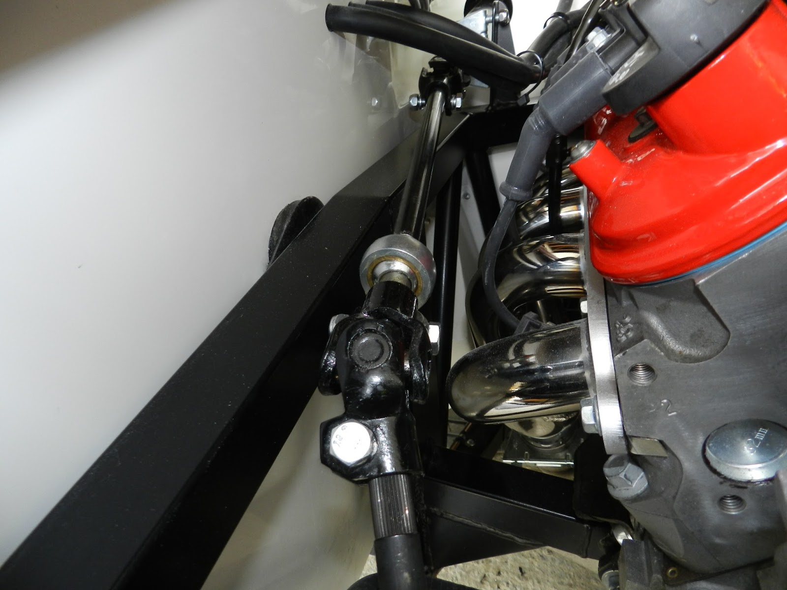 |
| Middle section connected to lower shaft. Rose joint can be seen here. |
 |
| Upper column connected to middle section. |
Once the nuts and bolts are tightened up, I will need to make sure that there are no tight spots when turning the steering wheel. If there are the joints will need moving around the splines.
Monday, May 30, 2016
ABCDE of Cobra building!
Accelerator
I have a fly by wire accelerator pedal, so the loom has provision for this. I drilled the holes for the fitting plate and a hole big enough to allow the connector to pass through. This was attached with M5 button head bolts and nyloc nuts. The plate was made by Keith Akerman, fabulous piece of engineering, as expected from him.
Brake and Clutch hoses
The hoses needed securing so as to comply with IVA requirements. Again a part made by Keith came in to play to secure the three braided hoses against the side of the engine bay. Another pair of hands was needed to fix this wit M4 screws, so Carol came to my rescue. A P-clip was used to secure the hoses to the reservoir.
Dipstick tube
This had bugged me for a while! So I thought that I had better sort it. The dipstick tube was the wrong shape for the LS6 engine. So using a pipe bender, I carefully reshaped the tube to avoid the headers and HT leads. Once it was the right shape, the tube was secured with a P-clip to the coil frame, after adding some rubber tubing to make sure that the tube would not move. It was fairly easy really. Don't know why I had kept putting it off.
Foot well Extension
Now it was time to fit the foot well extension. Again Carol helped, as my arms were not long enough. The extension was simply bolted in place, where it had been trial fitted before. I did apply some silicone to make sure it was sealed, both inside and out.
I have a fly by wire accelerator pedal, so the loom has provision for this. I drilled the holes for the fitting plate and a hole big enough to allow the connector to pass through. This was attached with M5 button head bolts and nyloc nuts. The plate was made by Keith Akerman, fabulous piece of engineering, as expected from him.
 |
| Accelerator pedal with connection made. Note split plate and grommet. |
The electrical connector was pushed on to the pedal until it clicked. Easy!
The hoses needed securing so as to comply with IVA requirements. Again a part made by Keith came in to play to secure the three braided hoses against the side of the engine bay. Another pair of hands was needed to fix this wit M4 screws, so Carol came to my rescue. A P-clip was used to secure the hoses to the reservoir.
 |
| Hoses secured |
This had bugged me for a while! So I thought that I had better sort it. The dipstick tube was the wrong shape for the LS6 engine. So using a pipe bender, I carefully reshaped the tube to avoid the headers and HT leads. Once it was the right shape, the tube was secured with a P-clip to the coil frame, after adding some rubber tubing to make sure that the tube would not move. It was fairly easy really. Don't know why I had kept putting it off.
 |
| Dipstick fitted and secured to coil frame |
Now it was time to fit the foot well extension. Again Carol helped, as my arms were not long enough. The extension was simply bolted in place, where it had been trial fitted before. I did apply some silicone to make sure it was sealed, both inside and out.
 |
| Not the prettiest of jobs, but hopefully effective |
Sunday, May 29, 2016
Door cards/leather panels
Apologies for the lack posts recently, but a pending house move has taken it's toll on the Cobra build!
Door cards
The door cards are the leather covered door trims. The leather is mounted on thin MDF and has holes pre-drilled for the clips and door handle spindle. The latter's position is not obvious at first! The hole is the one with the arrow in the photo below.
The clips to fix the cards were green things, located in a bag in the door card pocket. I put masking tape on the door first, then offered up the card. I cut out the hole for the door spindle carefully, removing the foam. Some people use a hole punch here. The clip was inserted into the relevant hole in the door card. It was then marked on the back with black marker pen. This then transferred to the masking tape to give a hole centre to drill in the door (7mm).
This was repeated for the other clips, working along the top first, until all the holes were drilled and the card could be clipped in place. This is simply a case of pushing the clips with a thumb until it clicked. This left indentations in the leather that soon recovered.
On the first door the door card lined up fine. On the second, I didn't check it properly and found that it overhung by a couple of millimeters and fouled the lock. That was after I had fully fitted it. Here I had to refit the piping a little to avoid the lock. So if you are doing it check this out before you drill any holes in the door!
Door cards
The door cards are the leather covered door trims. The leather is mounted on thin MDF and has holes pre-drilled for the clips and door handle spindle. The latter's position is not obvious at first! The hole is the one with the arrow in the photo below.
 |
| Rear of door card |
 |
| First hole drilled |
 |
| First card in place |
Wednesday, May 11, 2016
Fuel tank
Roll hoop escutcheon final fixing
Remember that I had one of the 18 bolts "disappear"? I thought that I would have to fill the hole with resin and then tap the hole for the fixing bolt. However, after talking to a few fellow builders and to GD, I decided to try wedging the bolt with a small sliver of wood and then screwing it into the hole. It worked and held the escutcheon in place! So roll hoops now complete.
Fuel tank
Now the roll bars, grommets and escutcheons were fitted, my attention turned to the fuel tank. Earlier I had installed the fuel lines and the fuel pump wires through the boot floor.
The dip tube sensor was fitted to the tank with five M5 rivnuts and bolts. The tank had to be drilled with 7mm holes for the rivnuts and the swarf removed with the vacuum cleaner.
The sensor was then secured with the five M5 bolts, using the rubber gasket and some Hylomar sealant.
The tank was then manoeuvred into its final place. Then the hose unions were connected to the tank using Loctite 572 on the male part of the fitting (not the threads). I removed a small amount of GRP, using the Dremel, at the saddle of the boot floor and where the filter went to give a little clearance. I also used a small amount of Hylomar on the threads.
Straps were needed to secure the fuel tank. These were fabricated from 50mm x 2mm stainless steel. The straps were bent to match the shape of the tank and holes drilled in each end of the straps to secure them to the body. Stainless steel is a pig to drill - I burned out 6 drill bits drilling just 4 holes! M8 nylocs nuts with bolts went through the boot floor and 2 x M5 button head bolts with rivnuts were used above the differential for each strap. GD suggest using self tappers at over the diff, as the strap is in sheer. However, I reckoned that over a bump the strap would be in tension, so either a nut/bolt or rivnuts would be better! Rivnuts were easier to fit, so that option won the vote. A few small strips of neoprene were used on the straps to isolate the straps from the tank.
The sensor cable was then attached to the main terminal and the two earth wires, from the loom and the filler attached to one of the tank studs. The carpet was fitted over the fuel inlet on the tank and then the joining hose was fitted. Next the fuel filler cap was refitted to the body with the new earth strap attached to one of the bolts. Finally the two hose clamps were tightened.
Heat shrink was put over the fuel pump cable, before ring terminals were attached to the cable and then heated to shrink it. A small amount of silicone sealer was applied around the cable and heat shrink joint to ensure that no moisture was trapped inside. This just added some protection to the terminals and wires in the exposed area at the rear of the chassis.
The ring terminals were connected to the fuel pump, the black going to the earth terminal (both terminals were a different size).
I expected that the boot would simply be a case of refitting the two bolts. No! I had to adjust the lid to get it to fit properly. Never mind it's all done now.
Photos
And a few photos, 'cos I can!


Remember that I had one of the 18 bolts "disappear"? I thought that I would have to fill the hole with resin and then tap the hole for the fixing bolt. However, after talking to a few fellow builders and to GD, I decided to try wedging the bolt with a small sliver of wood and then screwing it into the hole. It worked and held the escutcheon in place! So roll hoops now complete.
Fuel tank
Now the roll bars, grommets and escutcheons were fitted, my attention turned to the fuel tank. Earlier I had installed the fuel lines and the fuel pump wires through the boot floor.
The dip tube sensor was fitted to the tank with five M5 rivnuts and bolts. The tank had to be drilled with 7mm holes for the rivnuts and the swarf removed with the vacuum cleaner.
 |
| Five holes made and rivnuts fitted |
 |
| Dip tube sensor fitted with gasket and Hylomar blue sealant |
 |
| Not a lot of space! |
 |
| Top strap fixings |
 |
| Tank in place with straps |
 |
| Tank and carpet in place |
 |
| Heat shrink over exposed pump cable connections |
 |
| Electrical connections made |
Photos
And a few photos, 'cos I can!


Subscribe to:
Posts (Atom)