Thursday, November 26, 2015

Windscreen, washer jet and stay

Initially I applied masking tape to the scuttle and marked the centre lines for the washer jet and wiper spindles. The spindle centres were marked at 415 mm from the outside of the stanchions. With the washer jets I had decided, like most, to only fit one double jet even though two were in the kit. This was marked up on the centre of the car.
Spindle and washer jet centres marked
Washer jet

The centre of the washer jet hole was marked 45 mm from the screen rubber and 20 mm back from the bonnet recess on to some masking tape. An 8 mm hole was drilled through the scuttle. The jet was fed through the hole and the supplied nut was used to secure it from underneath. The angle of the jets will need adjusting once power can be applied to the pump.
Washer jet fitted
The clear plastic water tube was then cut and fixed to the jet and to the washer bottle pump. This was simply pushed over the tails (you may need to warm the end to do this).

Windscreen centre stay

This should have been an easy job, but like many this didn't turn out to be the case! The stay consisted of three parts plus two screws. The stay was put to one side. The lower part of the bracket was bent a little more to reflect the angle of the screen. The two brackets were made up in to one bracket and fitted to the bottom of the screen in to the two pre-tapped holes using the screws supplied (at this stage the screen was off the car). The screen was then offered up to the body.
Two brackets made in to one and attached to screen
With the screen in place, it was clear that the bracket was about 3 mm above the scuttle. Problem! A quick call to Andy helped solve the issue.

Each screen is handmade and this means that the tolerance is quite wide. The answer was to elongate the stanchion holes and drop the windscreen to close the gap and put a little more compression on the rubber strip.

So screen off again. Stanchion legs and cross braces removed. The fixing holes were then elongated to allow the screen to drop a few millimeters.
Stanchion hole elongated a little
After a few attempts, the holes were opened out the right amount. I needed patience here and so did Carol, who was roped in to help put the screen on and take it off .... quite a few times. The stanchions and cross braces were loosely fitted to the car. Then the windscreen fitted and measurements checked again. Now the stay bracket fitted flat to the scuttle. Phew!
Stay bracket in place
The screen screws and bolts were tightened up to stop the screen moving and measurements taken. After a little bit of adjustment, the measurements were spot on.

The next step was to fix the windscreen stay. In theory a simple job, but due to the size and angle of the bracket it took an age. To tighten the button heads, I had to grind down an Allen key a little. I expected this to be the worse part, but no. The bracket was fixed to the scuttle using nyloc nuts and washers. Next the stay was fitted. This involved hooking one end over the top of the screen and the tightening two nuts at the bottom around the bracket. What a job! I definitely needed patience here.
Screen stay in place
So now it is done. Just need to remember to apply silicone around the stanchion legs and escutcheons, to keep the water out.

Thursday, November 19, 2015

Engine and clutch parts arrived

Engine and clutch parts

It is 18 weeks since I collected the engine from Kyle at Tim Adams Racing Engines. It was 15 weeks since I returned the flywheel, clutch plate, clutch cover and alternator as they were not as agreed. After emails and phone calls, the replacement clutch and other parts have now arrived. The flywheel and clutch plate are good. The new belt tensioner, which was not on the engine when collected, has also arrived. However, the alternator is damaged and not as expected and I still do not have the dyno video.
Flywheel, clutch and alternator
I was expecting a used alternator, but got one with a broken plastic casing (the second one). I have now been offered to refund the cost of the alternator, but won't hold my breath. So I now need to source a new one. More money :(

The ECU, engine loom, immobiliser and the lambda sensors from Canems were as expected and their subsequent service has been second to none.

I can now get the flywheel, clutch plate and cover installed on the engine. The engine assembly can then be mated to the gearbox (once I have a modified clutch release mechanism from GD) via the bellhousing before fitting to the chassis. Also I have just received a new "hi-torque" starter motor from Roadcraft to replace the used one I had broken a contact on!
Shiny new starter motor
Bonnet gas struts

The other gas strut is now fitted. So that's another job completed, except for the locking mechanism!

Edit: I have changed the ball stud and this is better. It positions the strut more upright, however the locking mechanism is still too big to use. 
Second gas ram now fitted
A note of caution here on the bonnet. If you have the body on the frame and an electric garage door opener where the motor moves along the track - watch that the motor clears the bonnet when it is open. Mine didn't, so a bit more gel coating to do on the edge .....

Wednesday, November 18, 2015

Bonnet gas struts

I have decided to fit adjustable gas struts to the bonnet, rather than the standard GD opener, even though I have been warned off by GD. I have seen a number of Cobra type cars with them installed for both the bonnet and boot, including GD, AK and Dax, but I have not yet decided what to do with the boot.
Simon Smith's AK with gas struts
If the pressure exerted is too great, the GRP can become distorted. So I knew that I needed adjustable gas struts and brackets that would spread the load to avoid any distortion. After contacting SGS Engineering in Derby, I was convinced that I could install gas struts successfully, using my own brackets.

Using the bonnet stay purchased from GD, I calculated the length of struts to order. I decided that 8 mm diameter was adequate - this is the rod diameter. I then worked out the stroke and the extended length that I required, which was around 220 mm and 470 mm respectively. The nearest gas strut stroke that SGS offered in their NitroLift range was a 200 mm stroke with an extended length of 450 mm (measured to the shoulder of the cylinder) - part number GSV8-200.

The end fixings ordered were 10 mm ball stud type and this adds 25 mm to the end of the centre of the fixing, with an M6 male fitting. This will give an extended length for the strut of 500 mm (450 + 25 +25) and a stroke of 225 mm (200 + 25) which should be ok. The total cost was around £45, plus the brackets etc, so say £50.

To keep the bonnet stays open, with the bonnet lifted, I also ordered a safety lock for each strut. These did not fit - see later!

Thanks to Rob here for the guidance - see the link to his blog to the right of this article.

Lower fixing

To locate the strut to the inner wing, I made a pair of brackets from 25 mm angle 3 mm aluminium, with three 6 mm holes (one in the centre for the strut location/pivot point). The brackets were 250 mm long and fitted up behind the lip of the engine bay. One needed a small amount of filing as the return was slightly smaller.
Bracket with three 6 mm holes
The front of the bracket is located above the suspension cut out - just make sure that the central hole (the pivot) is at the same point on each side). With the pivot point here the strut should be upright when the bonnet is open. Before fitting the bracket, the position of the three holes were marked on the GRP and opened out to 6 mm.
Hole positions for the bracket
Each bracket was fixed in place with two M6 button head screws and nyloc nuts, the pivot from the gas strut and some No More Nails. Nut lock was applied to the pivot nut.
Bracket fixed in place
Upper (bonnet) fixing

The cylinder of the strut was positioned at the end farthest away from the body fixing point (nearest to the windscreen). The other end was fitted to the pivot point on the body. I then compressed the gas strut (after releasing the pressure for about 15 seconds [apparently this reduces the pressure from 700 N to around 250 N!] - but check your own struts for this) and marked the pivot position on some masking tape attached to the wing. The distance was 300 mm from the centre of the body pivot. I then transferred this to some masking tape on the bonnet.
Pivot position marked on wing and bonnet
For the top brackets, the ones that fix to the bonnet, I again used some more aluminium angle (I was going to use 'T' section to keep the load in the centre, but the fixings would not have been ideal on the bonnet ribs, as they are relatively narrow). I made the brackets 200 mm long and shaped them to leave a fixing lug at the centre for the ball stud pivot.
Off-side bracket
Four 6 mm holes were drilled in each bracket, two either side of the pivot. For the pivot point another 6 mm hole was drilled - 12-14 mm in from the 90 degree return of the angle (this is to avoid the strut fouling the capheads).  The brackets were then used to mark the holes to drill in the underside of the bonnet rib  for 6 mm rivnuts. The holes were drilled, the rivnuts inserted and then the brackets were secured to the bonnet with button head bolts.
M6 rivnuts in place
Once the strut had been fitted, the pressure was checked. The strut was adjusted by opening the hex adjuster for about one second at a time (this should be done the same amount on each side until the struts exerted just enough pressure to hold the bonnet open).
Strut from inside the engine bay
Strut from outside the car
Finally, I tried to fit the SGS locking tubes. These are designed to keep the bonnet open, even in winds. However, I found that the tube was too wide and fouled the body, so couldn't be used.
Locking tube fouled the lower mounting point when the bonnet was lowered
Now I just need to do the other side!

Tuesday, November 17, 2015

Cobra chassis is born

Steve Hughes picked up his GD427 body and parts today. He saw my Euro chassis being prepared and took photos. I decided to have it powder coated in black. So here it is before it is kitted out as a rolling chassis by GD!
View from the front
View from the rear

Monday, November 16, 2015

Tyres and stoneguards fitted!

Tyres

I had Michelin Pilot Super Sport tyres fitted at home today. 245/40/ZR18Y at the front and 275/40/ZR18Y at the rear.

The wheels were delivered to my house directly from Image, although I had ordered via Gardner Douglas. This was no more expensive than ordering direct from the manufacturer, so well done GD. Having them fitted on the drive saved me having to take the wheels to a fitter and also having to wait around at a fitters place, kicking my heels.

I used "tyresonthedrive.com", they were competitive on price and fitted the tyres and balanced them at home.  I could have bought just the tyres cheaper, but then I would have had fitting and balancing costs, plus fuel to get to a fitter and all the hanging about. So in the end it would have cost me more.

An email in the morning reminded me that the tyres would be fitted today. The fitter (James) arrived on time as promised, in his van with electric fitting and balancing on board.
Tyresonthedrive - tyres being fitted
The centre nut cover and spinner was removed from each wheel first. The tyres were fitted without any fuss in about an hour and paid for at that point. Now if all services were that good!
Tyres fitted
Now I just need to remember to take them to GD when I collect the chassis (this looks to be delayed a bit at the powder coaters according to Andy).

Stone guards

Black stone guards contrast nicely with the white body. Black was not only chosen due to the contrast, but I know from experience that the Caterham's stainless guards were wrecked within a few weeks due to stone chips. Carbon fibre are available, but the cost was more than I wanted to pay and I couldn't find proof that they lasted much longer. That left GRP which can be rubbed down, filled and polished back to new if required.
Stone guard and rubber U channel strip
Black rubber U-channel edging was fitted around each stone-guard. The guards were fitted with a black rivet in the corner nearest the body. A hole was drilled in the corner closest to the body to accept the rivet. Then two black self tapping screws were used to fix each guard to the wheel arch return.
Stone guard fixed in place
The wheel arch was then dressed back to the stone guard, so that there was no white showing. How good does that look?

Can't wait for the chassis now!

Sunday, November 15, 2015

Brake and clutch pipes

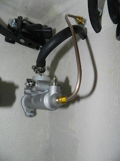
The brake and clutch master cylinders had been fixed in place and so had the flexible braided hoses that will connect the body to the chassis union. The positions on the chassis connection block are nicely etched on from what I have seen. The silicone hoses that link the reservoirs to the master cylinders were also in place, but as yet not connected. So 'all' that was required was to connect them. Easy ..... or so I thought!

The 'output' braided hoses (pressure) had already been attached to the inner wing using the three 10 mm holes and the 'input' silicone hoses (from the reservoirs) had been fed through the three 15 mm holes I had drilled earlier in the inner wing between the engine bay and the compartment behind the wheel arch. The input and output hoses had been installed in the following sequence (from the front of the car):
  • Front brakes
  • Rear brakes
  • Clutch
I had installed the brake and clutch cylinders in the same order on the bulkhead from left to right (when viewed from within the compartment behind the off-side front wheel).
  • Front brakes - 0.75" cylinder
  • Rear brakes - 0.625" cylinder
  • Clutch
Clutch pipes

The copper clutch pipe was identified in the GD kit (it was the shortest one marked No. 10 on the yellow sleeve). The silicone hose from the clutch reservoir to the clutch master cylinder, was connected to the white plastic hosetail, using a pipe clip to secure it. The plastic union was removed from the master cylinder to make this a bit easier. The copper clutch pressure pipe was bent so that it fit between the front of the clutch master cylinder and the rear braided output hose (see blow).
Clutch master cylinder with connections made
Brake pipes

Now read this carefully and take on board. I hadn't!

I had initially tried to connect the unions pre-fitted to the brake pipes to the front ports, assuming that the input pipe would go to the rear ports, like the clutch cylinder. After a conversation with Andy, who was totally confused with what I was doing, it turned out that I had been trying to fit the Jaguar unions in to the two master cylinders that had been supplied. Andy thought that he had explained what was needed to me, hence the confusion.

The rear ports are actually 3/8 UNF and take the pressure pipes. The front are 7/16 UNF and take the silicone input pipes from the reservoir, via brass hosetails.

I had not appreciated the correct fitting or the changes required. So the brake pipes had been bent before I realised that the fittings on the pipes were wrong and that I was trying to fit them in the wrong holes!

I didn't have any of the unions which should have come with the brake pipes/cylinders. After the conversation and a few photos by emails, Andy at GD put me on the right path and sent me the missing parts.
The brake unions
The unions on the pipes supplied by GD, No. 11 and 12, needed changing to the 3/8 UNF unions (the bottom two in the picture above). My flaring tool kit came in useful for this (the pipes were originally for the Jaguar tandum master cylinder which uses M10 and M12 connectors, my car has two separate brake cylinders connected via a balance bar). Are you still following this?
The bent brake pipes plus the unions that need swapping
So with the correct fittings on the copper pipes and the brass tails for the silicone hose I started again.

Remember that the brake pipes are attached to the rear output holes. This is the reverse of the clutch master cylinder just to make things more interesting. The copper brake pipe was re-bent and attached, so that each pipe linked the cylinders to the appropriate braided hose previously fitted. I found that attaching the pipes to the master cylinder first, then to the braided hose fittings on the inner wings was the easiest method to avoid cross threading (loosen the nuts on the braided hose first).
Copper pressure pipes attached to the rear ports
The silicone hoses were then connected to the new brass hosetails (remember to use the supplied Dowty washers - the ones with rubber around the inside) on the front of each brake cylinder. The hoses were clamped in place with pipe clips.
Silicone hoses from the reservoirs in place
Now, when Andy checks the brakes before the IVA test, he may need to swap the master cylinders around to get the correct pressure at the back and front!

NOTE: This wasn't required, but the balance was corrected as expected.

Saturday, November 14, 2015

Fuel filler cap

Mr IVA has a requirement (not unreasonable), that all fuel filler caps are tethered to the car so that you can't drive off from the petrol station and leave your filler cap behind! The flush cap as supplied, was not tethered to the filler neck. An Aston type filler would not need this work.

I used picture hanging cable, the brass looking stuff, as it was thin and corrosion resistant.
The cable and fixings. The 'modified' connection is on the left see below
The cable was to be attached to the filler cap, then to the neck of the filler itself. About an 200mm length of this cable was required for this (plus the amount needed to secure the cable - in my case an extra 80 mm).

To achieve this, a hole was drilled in the bottom plastic part of the cap, taking care not to affect the locking mechanism. The cable was fed through the hole and secured to itself using a modified electrical connector. The 'modification' is a pompous way of saying cut off the connection part and discard it!
The cable attached to the black plastic of the filler cap
The other end of the cable was attached to the filler neck. Here a small hole was drilled in the bottom of the neck to take the cable. A small channel was also cut in the filler neck, with the Dremel, to allow the cable to be flush once the pipe that connects the filler neck with the fuel tank is fitted.
The filler neck showing the hole and channel
This secures the filler cap to the filler neck and should satisfy the IVA requirements.
The finished tether


Wednesday, November 04, 2015

Wheels arrived!

The wheels have arrived from Image Wheels. I had decided to go with black centres, annodised rims, nut covers and spinners. I had Image wheels on the racing Radical, so I am confident that they will be okay. They are their GTD5 Halibrand replica style at 18" diameter, 8.5" wide at the front and 10" wide at the rear!
The four wheels with spinners and nut covers
Now I just need to organise some tyres, prior to collecting the chassis from GD in Newark. The GD preferred tyre sizes are :
  • front 245/40/ZR18 Y
  • rear 275/40/ZR18 Y 
I will go for Michelin Pilot Super Sports as they are rated as good in the wet/damp, are excellent in the dry,  have good reports for comfort, are rated as one of the fastest tyres, have raised ridges around the tyre bands to help defend against kerbing and get great reviews. They sound pretty good!

Tuesday, November 03, 2015

Boot lock, bonnet rubbers and fuel filler breather

This was a job I have been putting off!

Boot lock

First I marked the centre of the car (this is not as easy as it sounds!), then using the lock, handle and striker plate, I marked the square bar position in relation to the top of the striker plate (at this stage it is not possible to work out the hole location in the boot lid).
Centre line marked
The round bar on the striker plate was aligned with the edge of the square bar to the left of the centre line, so it was about 2.5 mm off centre (to the near side of the car) of the square bar.
Centre line with striker plate located. The striker bar looks further away from the centre line than it is.
The distance is half of the square bar to the near-side of the centre line.
An undersize hole was then cut (in case I made a hash of it) with the Dremel, where the claw of the lock would go. The striker plate was fitted to the car with button head screws and nylock nuts.

I then climbed in to the boot to mark out the position of the lock mechanism. The position was identified by hooking the claw around the striker plate bar and getting Carol to press lightly on the boot lid from outside (she let me out eventually). The lock fixing holes were then marked and drilled. After fixing the lock in place with self tapping screws, a 3 mm pilot hole was drilled in the boot rib, using the square hole in the lock as a guide.
Lock first fit and pilot hole drilled through boot rib
The pilot hole was opened out to 10 mm using a stepped drill, to avoid chipping the gel coat. A hole was then drilled through the outer skin, using a 3 mm bit from the boot side, which emerged very close to the centre line. Using the pilot hole, the external hole was then drilled to 20 mm.
The two holes (one in the outer skin and one in the inner skin) can be seen in the boot lid.
The outer skin hole was opened up to centralise and locate the handle. The slots were cut for the locating lugs. The handle was fixed with the two self tapping screws after the square bar was pushed through the lock.
Loosely fitted handle, square bar (too long at this stage) and lock.
The square bar was marked then removed with the handle. It was then trimmed to the marks so that it was flush with the lock. The lock was then finally refitted and the handle put in place.

Lock fitted in place and tightened up
A small amount of silicone was applied to the handle fixing, before final location. Nice feel when closed and locked!
Handle fixed in place
Whilst I was at it, I fixed the number plate light, where the chrome cover would not tighten up - the thread had stripped. Here I super glued a standard nut behind the hole on the light unit. The fixing bolt was then put in place and tightened.

Bonnet rubber strips

This was an easy win! 

The black sealing strip was fixed in place, using the self adhesive backing. It is not a continuous run around the bonnet shut line, but rather three separate strips. This apparently allows some ventilation and avoids the bonnet being raised too much above the body line, which a continuous run would do.

The edge closest to the windscreen was run from the edge of the curve of the bonnet shut line on the off side, across the car, so that it was equal length from the near side corner. See photo below.

The side strips were then cut to the same length as each other and fixed to the shut line from the end of the corner nearest the windscreen, towards the front of the car. See photo below.
Rubber seals in place
This raised the bonnet very slightly, but with a slight compression it allowed the locks to operate and close without any free play. Sorted!

Fuel filler breather

A breather adapter was required for the fuel filler.

An 8 mm hole was drilled in the neck of the filler. Care was needed when selecting the position so that the cap would still fit and lock once the breather adpter was in place. The hole was tapped to 1/8 NPT. This may seem an odd thread, but I had a tap already in my Draper metric tap and die set!
Filler, cap and adapter
The filler cap was put loosely in place on the body. A small amount of nut lock was applied to the thread of the fitting before it was screwed in place. 
Breather hole can be seen in the neck 
The filler was rotated so that the breather was facing towards the drivers door, before fixing with the six fixings provided. 
Breather position viewed from inside the boot towards the off-side rear wing
Copper pipe brake pipe will be added later. This will need to be in an 'S' shape and use the compression fitting of the adapter. The other end will go through the boot floor - I need to remember to keep it away from the exhaust or Mr IVA will not like it. Don't think I would either if it ever vented fuel out there!

Sunday, November 01, 2015

Final windscreen fixing

Previously I had trial fitted the windscreen without bolting it in place and then I had removed it. Hopefully this is the final fixing!

The stanchions were removed from the screen by undoing the four fixing screws on either side. The stanchions were then drilled, using a conical stepped drill, a drill and drill stand at the pre-determined places, to accept 8 mm button head machine screws. I had been warned that the stanchions were chromed brass and brass is liable to grab when drilled, so I had used the conical stepped drill with care. I had to turn the stanchions over and drill from the other side to get an 8 mm hole all the way through - had to do this due to the depth of the step on the bit.

The drilled stanchions were then re-attached to the screen and the screen put in place. Carol (my better half) came to my rescue here and lent a hand, as with over £550 of screen I didn't want to damage it. The screen position was checked and the bottom locating bolts/holes were opened up very slightly. A round file did the trick here. Penny washers were used to make up the small gap in between the fixed screen mounting points and the stanchions to avoid putting stress on the screen.
Near-side stanchion from inside the passenger compartment
The screen should be about 6mm off the scuttle at the outer edges and the top should be 930mm from the rear of the cockpit roll. The measurement from the first sun visor screw hole (I used this point as it was a good fixed reference) to the rear of the door openings should be close to the same on each side - in my case 810 mm. No need for the temporary locating templates that many of the older builds have entailed. All the measurements were correct - whoopee! Well done GD.
Windscreen in place
The screen was then unscrewed from the stanchions, leaving the uprights in place.


Stanchion with silicone sealer
The slots were sealed using silicone and then each of the escutcheons was fed over the stanchions. The escutcheons were bent to the shape of the body and then fixed using two self tapping screws. A small amount of silicone was used to seal the escutcheons.
Windscreen escutcheon

The under dash cross bars were fitted to the same holes as the screen stanchions. a small amount of silicone kept the penny washers in place! Ideally this whole job should have been done when I fitted the stanchions and before I siliconed the things in place - it would have been a bit easier!
The two cross bars fitted
The way the two bars are fitted can be seen in the photo above. They were secured using the button head screws that fixed the windscreen stanchions to the body.
A view showing the two cross bars in place
The two bars with the fixing lugs for the central under dash tray
Holes were drilled down through the transmission tunnel and rivnuts fitted to secure the larger bar to the tunnel. This can't be done finally until the carpet if fitted.
A side view of the fixing, where the rivnut and screw can be seen
Other shiny bits

Whilst I was at it I fixed the door hinge escutcheons. I like this bling stuff - must have been a magpie in a former life!
Shiny bits. Also you will see the courtesy light switch between the hinges
Just needed to open out the holes a little with a flat file to avoid the hinges touching the bit of the escutcheon that fits in to the hinge hole.

New link

I have added a new link to Jonathan's Cobra build - see 'Some other GD427 Cobra build blogs that may interest you' to the right of this post. Jonathan is the guy in the Shetlands who has just taken delivery of his GD.