Wednesday, December 30, 2015

Gearbox and headers

Transmission location

After some playing about, I found that the initial location of the gearbox was okay. If I moved the gearbox to clear the bolt on the shifter locating plate, the bell housing touched the chassis. So this was not an acceptable option.

The real problem was the location of the fuel line.
Fuel line ran on inside of chassis rail. Shifter cover plate removed and taped over to stop contamination
I moved the fuel line to the under side of the chassis rail. To do this I drilling out the rivets holding the clamps and re-fitting them on the underside of the chassis rail. A bit fiddly, but worth the effort.
Fuel line clipped to under side of chassis rail (looking up)
This gave about 15 mm clearance to the chassis, plenty of room.
Clearance can now be seen between the chassis rail and the shifter location plate
Now the locating plate was bolted back in place, using a small bead of Heat Resistant silicone to seal the plate. This required the tail of the gearbox to be lowered to allow the front off side bolt to be fitted.

Headers

Now it was time to fix the headers in place. The gasket was pre-marked with the manifold side and the orientation. A small amount of Heat Resistant silicone was applied to the block side of the gaskets and to the manifolds. These were then clamped in place with five high tensile bolts at each side.
Shiny header/manifold fitted
Another view of a header in place

Tuesday, December 29, 2015

A short time in the garage

Tidied up the garage today. Got rid of the transmission box and other rubbish. Space to work now.

Transmission

Not much progress today, but I took off the transmission tunnel cover to enable me to get at the shifter and get the 'box out of gear so that I could move the chassis.
Tunnel cover removed
Once the cover was off I discovered that a bolt head on the shifter locating plate was touching the fuel line on the inside of the chassis.
The top (near side) bolt can be seen against the fuel line
The shifter locating plate had been removed to aid installation, so it wasn't apparent that it was out of line. Now I need to move the gearbox over a little to gain some clearance. I will need to slacken off the engine mounting bolts as well as the gearbox mounting bolts to achieve this. Mustn't forget to thread lock the bolts again.

Engine

I put the spark plugs back in the engine and cleaned it up a bit (mainly the plastic plenum on the top of the engine).
Another engine shot, this time after cleaning up
The chassis with engine and gearbox in place looks brilliant, even if I do say so myself.

Monday, December 28, 2015

Installing the engine and gearbox

Attaching gearbox to engine

The hydraulic pipes were attached to the release bearing (see photo below), using a small amount of Loctite 572 on to the tapered surface, making sure not to get any in the pipes. Do not apply top the thread.

The end of the gearbox output shaft was lubricated with a little grease. Using the engine hoist and a couple of slings, the gearbox and bell housing were offered up to the engine.
Engine and gearbox being aligned
The shaft went through the clutch plate and entered the spigot bearing. Making sure that the shaft was lined up, the bell housing was then twisted a little and pushed home over the locating pegs. The bell housing was then bolted up to the engine block using high tensile bolts and torqued to 37 ft lb. Thread lock was applied to these bolts before tightening.

Gearbox mount

The gearbox mounting was fixed to the gearbox tail with two high tensile bolts and thread lock used.
Gearbox mount in place
After painting the mounting bracket with POR 15, it was loosely fitted to the chassis with high tensile bolts and nyloc nuts. This allows a small amount of movement in order to line up the gearbox mounting bolts with the plate. 


After fitting the gearbox, bell housing and the engine together, it was time to put the unit in to the chassis.

Fitting the unit in to the chassis

To get the unit in easier, I took off the radiator support frame and the two removable cross member from the front of the chassis (the top brace and the diagonal).
Removable cross brace (top right) and diagonal brace
Radiator support frame and cross-braces removed from front of chassis
The engine mounting adaptor plates had been fitted to the engine earlier, but the rubber mounts were removed after the trial fit. Each mount was greased, after removing the 'bump', to deter rust. These were put to one side.

I also put the box in to first gear to stop it moving when fitting the prop shaft. At the same time I removed the gear shift mechanism from the tail of the gearbox by taking out the six bolts and gently prising off the plate. The remaining silicone was removed at this stage.
Gear shifter removed
Now I enlisted help to get the unit in to the chassis, in the form of son-in-law Matthew.

Two slings were attached to the hoist after feeding them under the engine and bell housing. I couldn't have done this task on my own, not enough hands!

Using the hoist and gently moving the chassis, we manoeuvred the assembly in to place. A careful stepped motion (i.e. lower, push in, lower etc) was used on the hoist to get the assembly into the chassis. The LS6 engine has the batwing sump and this went under the engine mounts on the chassis. The prop shaft was inserted in to the tail of the gearbox, lubricating the gearbox seal with the gearbox oil.
Engine and gearbox unit on the hoist
Matthew aligning the prop shaft
After a lot of jiggling, the unit was in place. The engine mounts were then slid in to place, over the chassis mounting points. The long bolt and nut were used to secure the mount to the chassis. The three supplied hex set screws were then inserted through the mounting in to each adaptor plate, after a bit more engine jiggling, using thread lock and tightened by hand.

The four bolts and nuts were used to secure the gearbox mounting bracket, after elongating the two mount holes. The two high tensile bolts were then used to secure the gearbox mount to the bracket.

All the bolts were finally tightened once the assembly was in place.
Engine fully fitted
Another view of the engine and gearbox in place
The whole process took two of us about five hours!

So now I have some space in the garage, after moving the engine, bell housing and gearbox.

Saturday, December 26, 2015

Rocker covers

As the rocker covers were a little rough to say the least, I decided to repaint them.
Poxy paint on rocker cover!
My first attempt with the red spray paint from Europa Spares and baking (as per the can), did not work. It looked ok prior to the oven, but came out bubbled! Not sure if this was the paint or the preparation by me. But whatever, it didn't work.

The paint on the covers was scraped off, treated with Nitromors, rubbed down with wire wool, to the bare aluminium then degreased.
Bare rocker cover
The rocker covers were then painted yet again, this time with high temperature engine enamel by brush. I tried one rocker cover first just in case! Red only seems stable up to 300 deg C (black and silver seem to go up to at least 600 deg), but I reckon for the rocker covers this should be okay. The paint, from Halfords, needs 80-90 minutes to become touch dry, but a second coat must be applied within two hours - so a 30 minute slot! This time it is a gloss red, which with hindsight, is better than the matt finish.
Off side rocker cover in place
I have done the one cover completely, the other side is now ready for painting. By painting the rocker covers, I may also avoid the need to add beauty covers, but we will see!


Wednesday, December 23, 2015

Carpets - couldn't resist

I couldn't resist trying out the carpets. I laid out the transmission tunnel and the outer sides, then added the rear bulkhead and floor. My excuse was to get rid of any creases! I think it should look brilliant against the white of the car..

So here is a quick pre-view! I am still undecided whether to have a black leather tunnel cover and rear section, but plenty of time to decide.
Carpets loose laid
Black leather seats, door cards and dash should set it all off nicely.

Sunday, December 20, 2015

Windscreen wipers

Wiper spindles

I had been pre-warned by Meena from GD that the central bundy tube may be too short, as their supplier had sent a batch of wiper assemblies and some of the bundy tubes had been found to be the wrong length. Mine was part of that batch. The spindle to spindle measurement on my car was 505 mm, which was 35 mm longer than the bundy tube provided. So GD arranged to send me a longer bundy tube with pre-flared ends.

After getting the new tube and before I attempted to drill the holes, I again checked that the bundy tube was bent to the same curve as the scuttle. The wiper mechanism was again assembled on the bench and the spindle distances checked against those marked on the scuttle. This time they only needed a millimeter adding to the markings.
Wiper mechanism bench fitted. Note: the motor is facing the wrong way
The outer edge of the rubber washers were then marked at 5 mm from the screen rubber and the eliptical spindle holes were marked on to masking tape using the inside of the washers. The centres of the holes were established and marked.
Offside spindle markings
The metal ferrule was used as a guide to drill the hole at the correct angle to the scuttle.
Drilling the holes
The holes were drilled under size initially, then gradually opened up with a hand file.
File used to open up holes
The spindle ferrules had to be ground down to get the same angle as the chrome ferrules and to expose a little of the spindle thread. The spindle mechanisms and long bundy tube were offered up from under the scuttle and the rubber washer, chrome ferrule and nuts fitted to the outside.
Trial fit of spindle
Both spindles finally in place
Wiper motor

Once I was happy with the spindles, the wiper motor was fitted to the cross brace using the U bracket/strap, with the rubber mount below it. At this point I realised that the piece of bundy tube that connects the motor to the nearside spindle was also too short by 10 mm.
Bundy tube to motor short
Luckily I had the short central tube that GD had replaced, so I made a longer tube to connect the motor to the spindle! I cut the tube 2 mm longer than required, then flared the end with a brake pipe tool, before fitting (not as easy as it sounds as the bundy tube is not soft copper). The electrical connector on the loom was then pushed in place and held by a long tie wrap (not shown in photo).
A new section of bundy in place and motor fixed in place
Finally the connection to the motor, the mounting bolts, spindle nuts and the chrome spacers were fully tightened. The park position of the motor will need to be checked once the power can be applied - the wipers park on the opposite side to usual.

A job I had been dreading was done.

Friday, December 18, 2015

Propshaft fitted

Propshaft

The propshaft is tiny. In fact when I brought the stuff from GD, I thought that they had forgotten to put it in with the other bits. But it was me who had overlooked it!

To make assembly easier, the propshaft is connected to the diff prior to installing the engine/gearbox assembly. The four high tensile bolts needed shortening, prior to fitting to the diff. These are fixed with nyloc nuts.
Propshaft bolted to diff
The yoke is already fitted to the propshaft (I had exchanged my yoke with GD). The yoke was lubricated with the gearbox oil so that the splined part of the yoke was ready to inserted in to the gearbox tail when the assembly is inserted in to the chassis.

Gearbox mounting

The gearbox mount was fixed to the tail of the gearbox. First I had to clean out the holes in the mount, which were full of rubber. Initially I carefully drilled the hole with a smaller drill, using the pillar drill, then gradually turned in the bolt until it would go home fully.
Rubber mount fitted to the gearbox tail
Thermostat housing

Due to the tightness of the engine bay on the GD, it is necessary to fit a straight thermostat housing. This is either a modified housing or a new purpose made one. I chose the latter. This is simply a case of replacing one with the other.
Straight thermostat housing

Thursday, December 17, 2015

Fitting the release bearing and bellhousing

Fitting the release bearing

The gearbox was lifted out of its box using the engine hoist. The hydraulic release bearing was located over the gearbox output shaft, with the outlets aligned with the slots in the gearbox. The release bearing was bolted in place with the two M6 set screws supplied. Both screws had locktite applied. The top hose is the bleed pipe.

Release bearing in place
The clutch release mechanism is a modified (by GD) hydraulic bearing, with braided hoses fitted. If a non-modified hydraulic bearing is used, you can't fit the braided hoses using the 90 degree connector!

To clear the hydraulic pipes, the gearbox holes needed opening out a little, so I used a burr in the drill to achieve this.
Slot opened a little in the gearbox
A SMALL amount (and I mean small, a smear is enough) of white pipe sealer (such as Loctite 572) is applied to the male end of the pipe fittings. As I didn't have any at the time, this delayed the mating with the engine.

Fitting the bell housing

The bellhousing was attached to the gearbox, using seven new high tensile bolts. These bolts were thread locked too.
Bellhousing attached to gearbox
The flexible hoses were still accessible to allow the Loctite 572 to be applied before the hoses were secured to the two outlets of the release bearing. This was important as the flexible hoses needed to be attached before the engine was fitted.

Next job is either to mate with the engine (if the 572 has arrived) or fit the propshaft.

Wednesday, December 16, 2015

Engine mountings fitted

Had a visitor today who brought gifts, well it is nearly Christmas. Steve Hughes arrived and we had a good chat and some scrummy cakes. Yum yum! Then he took some photos of my build so far. Hopefully they will not lead him astray.

The engine mounts

The adaptor plates supplied by GD were fixed to the engine block (remember it is a Chevy LS engine) with two long cap head bolts and one short countersunk set screw in the locations shown below. Nice bit of machining Mr Akerman. 
Adaptor plate in place on the nearside
The adaptor plates allow the GD supplied engine mounts to be fitted to the LS engine, after a little modification. The metal and rubber engine mounts had the "bump" at the rear ground off, so they sat flat on the adaptor plate, taking care not to get too much heat in to the mount. Here a bench grinder and a burr in the electric drill did the trick.
Engine mount as supplied
Modified engine mount
The engine mountings were trial fitted to the adaptor plates with one long (bottom) and two short cap head bolts and thread locked. The final fit is done whilst the engine assembly is fitted to the chassis.
Engine mount bolted to an adaptor plate. Remember this needs
removing prior to fitting in the chassis, to make it easier
Another shot of the nearside engine mount trial fitted
This was repeated on the other side.

Thursday, December 03, 2015

Cobra chassis here

Today I collected the rolling Euro chassis and various other parts related to the engine from GD. It was over a month later than I expected, partly due to supplier issues. However, I still had a few things to do on the body, so time was not wasted.

I have had AP brakes fitted, along with Pagid brake pads, as I wanted the thing to stop. I know it will go, with 480 bhp it should! My previous experience with Pagid Blue pads was brilliant. They are not cheap, but they worked from cold, on track and on the road. Worth the investment.
Chassis being strapped on to trailer at GD
Chassis on trailer outside GD
I collected the radiator, headers (manifolds to us English), the exhaust, the air intake, various fuel system parts, engine mounts, hoses, steering shaft, drive belt etc. So a big bill (it also included the wheels and carpets).

Some other cars/shells that were at the works today. The red one in particular looked awesome. Black base, maroon red, with a glitter lacquer on top and silver stripes. Yummy!

Wednesday, December 02, 2015

Cobra carpets arrived

The carpets arrived today. Wasn't expecting them until the end of the month, but got a call from Meena at GD yesterday to check that I would be in to receive them!

The car is white, so I have decided that I will use black and red to create a contrast. The carpets take on this theme too. Horizontal surfaces such as the floor and transmission tunnel top will be in black, whilst the vertical surfaces such as the sides of the transmission tunnel and sides of the cockpit, will be in a rich red. The boot will be in black.

The carpet colours are black CPBW7401 and rich red CPBW7404 from the Boyriven range. Because I had chosen two colours, there was a premium of £120 to pay, but I think it will be worth it.

So here are the carpet parts laid out, as received from the trimmers. I need to work out where each piece fits, although some are obvious.
Carpet set. Need to work out where all the bits go!


Tuesday, December 01, 2015

Clutch fitted to engine

Today I had to clear out the garage so that I could get in and to prepare a space for the Cobra chassis! I have a nasty habit of putting things down anywhere there is space. Not usually in the right place either. Then I try to find the tool or item again and spend an age looking for the thing. Anyway, the garage is fairly tidy now - at least for a day or two.

Engine anciliaries

The new starter motor and belt tensioner were fitted to the engine. Thread lock was applied to the bolts and they were torqued up to 37 ft lb (remember that the block is aluminium, so you don't want to strip the threads!)
New starter motor in place
New belt tensioner fitted
Flywheel fitting

I fitted the spigot bearing in the end of the crank shaft.
Spigot bearing fitted to centre of crank
Making sure that there was a small radius on the bolt holes on the flywheel, it was attached to the crank on the back of the engine hand tight with six new high tensile bolts (I used ARP bolts from Roadcraft). The bolt pack says  'DO NOT use any washers' here, so I didn't! The thread of the bolts were thread locked and under the bolt heads ARP Ultra-Torque lubricant was applied (this stops false readings when torquing bolts). The lubricant is supplied with the bolt pack.

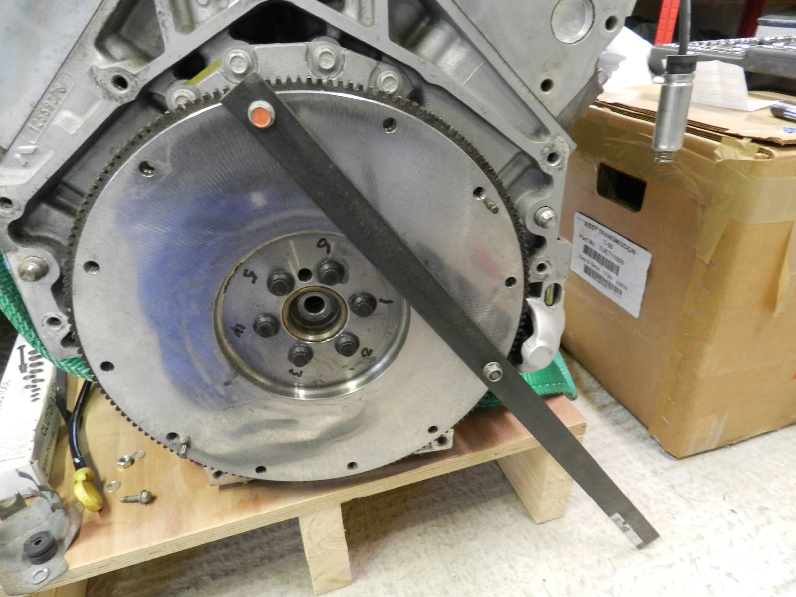
The bolts holes on the flywheel were marked 1 to 6.
Bolts marked with sequence numbers
The bolts were tightened in the following sequence 1, 4, 2, 5, 3, 6. Thread lock was applied to the bolts before they were torqued. They were tightened in three passes as follows:
  • 1st tighten to 25 ft lb torque
  • 2nd tighten to 50 ft lb torque
  • 3rd tighten to 85 ft lb torque
For the last pass, the flywheel needed to be 'locked', so a steel bar with two holes was used. This was bolted to the flywheel. The bar stopped the flywheel turning by making contact with a solid object (in this case the ground).
Bar made to enable flywheel to be adequately torqued
Finally any excess lubricant was removed from the bolt heads and the flywheel was given a clean.

Clutch fitting

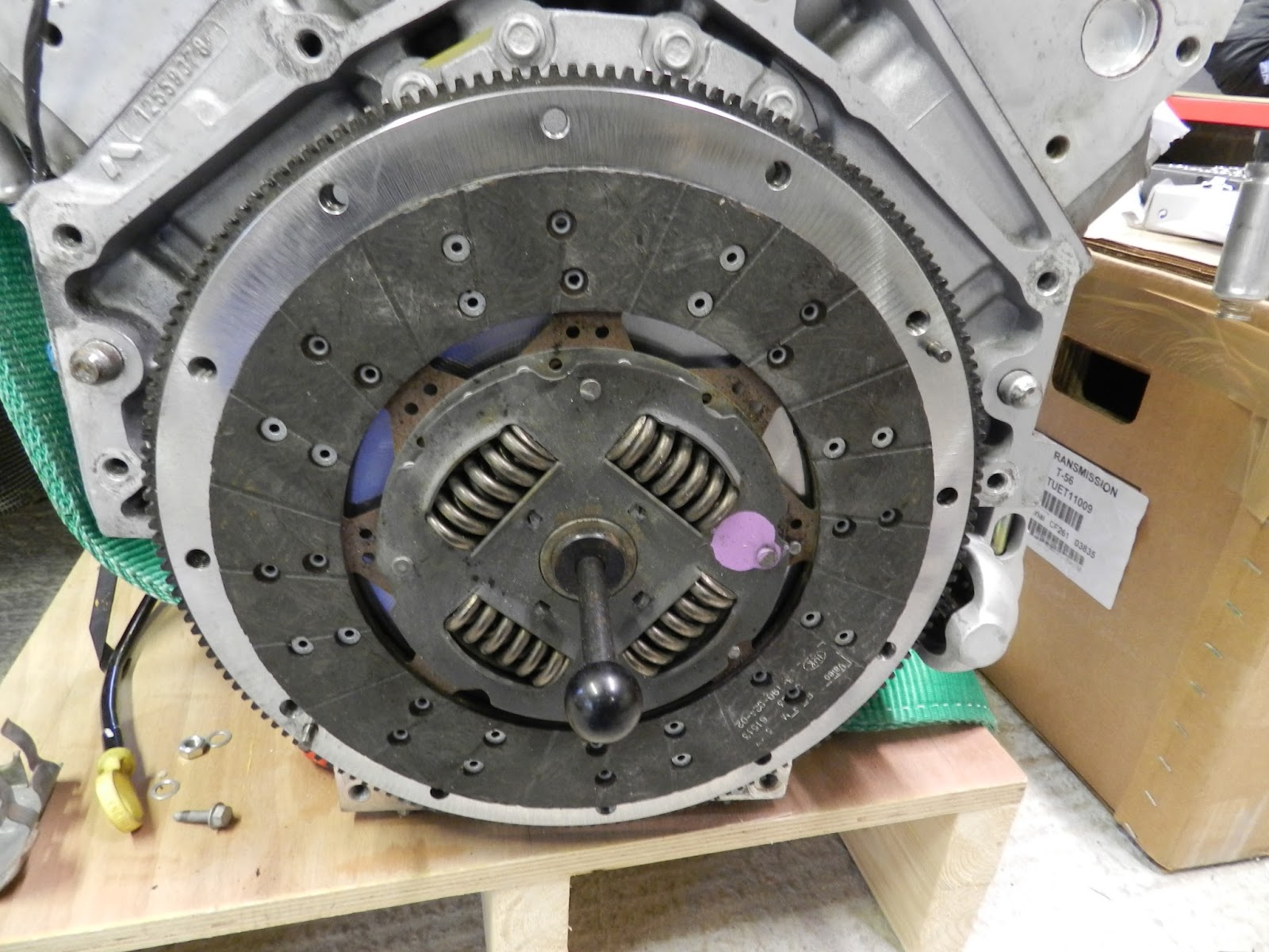
When the flywheel was fitted, the clutch plate was put on the flywheel (the clutch plate was pre-marked with the orientation on one face and it can really only go one way) and was held in place with the clutch alignment tool.
Clutch plate over clutch alignment tool
Thread lock was carefully applied to the threaded holes of the flywheel and the ARP Ultra-Torque lubricant was applied under the bolt heads. The clutch cover was put over the alignment tool on to the locating pegs.
Clutch pressure plate in place and ready to torque
Again the six bolts were tightened in three passes in the following sequence 1, 4, 2, 5, 3, 6. The torque for the three passes were as follows:
  • 1st tighten to 20 ft lb
  • 2nd tighten to 40 ft lb
  • 3rd tighten to 52 ft lb
As the torque for the final pass was fairly low, it was not necessary to 'lock' the flywheel. Instead Keith Akerman recommended (thanks Keith) that I tighten the bolts at the nine o'clock position. This stops the flywheel turning.

After the final pass, excess lubricant was removed from the bolt heads.