The 'output' braided hoses (pressure) had already been attached to the inner wing using the three 10 mm holes and the 'input' silicone hoses (from the reservoirs) had been fed through the three 15 mm holes I had drilled earlier in the inner wing between the engine bay and the compartment behind the wheel arch. The input and output hoses had been installed in the following sequence (from the front of the car):
- Front brakes
- Rear brakes
- Clutch
- Front brakes - 0.75" cylinder
- Rear brakes - 0.625" cylinder
- Clutch
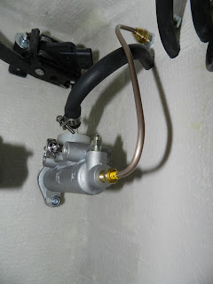
The copper clutch pipe was identified in the GD kit (it was the shortest one marked No. 10 on the yellow sleeve). The silicone hose from the clutch reservoir to the clutch master cylinder, was connected to the white plastic hosetail, using a pipe clip to secure it. The plastic union was removed from the master cylinder to make this a bit easier. The copper clutch pressure pipe was bent so that it fit between the front of the clutch master cylinder and the rear braided output hose (see blow).
 |
| Clutch master cylinder with connections made |
Now read this carefully and take on board. I hadn't!
I had initially tried to connect the unions pre-fitted to the brake pipes to the front ports, assuming that the input pipe would go to the rear ports, like the clutch cylinder. After a conversation with Andy, who was totally confused with what I was doing, it turned out that I had been trying to fit the Jaguar unions in to the two master cylinders that had been supplied. Andy thought that he had explained what was needed to me, hence the confusion.
The rear ports are actually 3/8 UNF and take the pressure pipes. The front are 7/16 UNF and take the silicone input pipes from the reservoir, via brass hosetails.
I had not appreciated the correct fitting or the changes required. So the brake pipes had been bent before I realised that the fittings on the pipes were wrong and that I was trying to fit them in the wrong holes!
I didn't have any of the unions which should have come with the brake pipes/cylinders. After the conversation and a few photos by emails, Andy at GD put me on the right path and sent me the missing parts.
 |
| The brake unions |
 |
| The bent brake pipes plus the unions that need swapping |
Remember that the brake pipes are attached to the rear output holes. This is the reverse of the clutch master cylinder just to make things more interesting. The copper brake pipe was re-bent and attached, so that each pipe linked the cylinders to the appropriate braided hose previously fitted. I found that attaching the pipes to the master cylinder first, then to the braided hose fittings on the inner wings was the easiest method to avoid cross threading (loosen the nuts on the braided hose first).
 |
| Copper pressure pipes attached to the rear ports |


No comments:
Post a Comment