
LS6 engine connections from Canems engine loom
Here is my take on the wiring for an LS6, but if you use this please do check it yourself as the engines do differ depending upon age. Yes it is a bit complex and boring, but is essential in getting the beast going! Apologies if this is obvious to you - it wasn't to me.
This might seem premature, as the wiring loom will not be installed until the body is put on the chassis - a few weeks away yet!
The first part of the notes below gives the loom connection tag on the Canems loom. The next bit is the number of wires. The final bit is where it goes on the engine. As I struggled, there are also some pictures of the sensors to help identify them.
Engine
The first part of the notes below gives the loom connection tag on the Canems loom. The next bit is the number of wires. The final bit is where it goes on the engine. As I struggled, there are also some pictures of the sensors to help identify them.
Engine
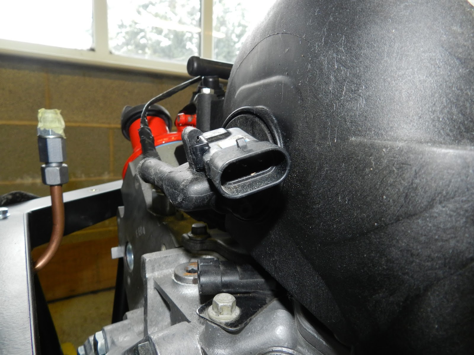
- Air temperature sensor (IAT) - 2 wire connector- fitted into air intake sensor on air intake tube

Air intake sensor - Alternator - 4 wire connector – alternator on nearside of car
- Alternator - 2 joined red wires with ring - alternator back, fixing post secured with nut

Small amount ground out of block to accommodate alternator

Alternator fitted, using GD spacers - Coolant temperature sensor - two wire - sensor in nearside head at top of manifold next to port 1.

Coolant sensor - Cam sensor - 3 wire connector - at front of engine near water pump, below throttle. There is also a cam sensor at the back of the engine (between the plenum and engine block) which is not used.

Cam sensor at front

Cam sensor at rear (not used) - Injector
1 - 2 wire connector - nearside injector 1 (front)

Injector connector


- Injector 3 - 2 wire connector - nearside injector 2
- Injector 5 - 2 wire connector - nearside injector 3
- Injector 7 - 2 wire connector - nearside injector 4 (back)
- Odd coil - 7 wire connector - on top of rocker cover nearside

Coil connector - Earth connection - 1 wire ring - to chassis
- Not marked on mine - round connector 1 - to GD Body Loom (different size to other)
- Not marked on mine - round connector 2 - to GD Body Loom (different size to other)
- Oil pressure switch - 1 wire 6.3 mm spade - oil pressure sensor to be installed Edit - location at rear of block currently blanked off

Where oil pressure sensor fits - Reverse light - 2 wire - to gearbox connector - front connector on gearbox with wire
- Odd lambda - 4 wire connector - nearside lambda in lower bend of manifold
- Odd knock - (mine was in the valley between the two heads) single green wire - discard the connector on the engine and do not use the black earth leads. Connect nearside knock lead of loom to rear sensor

Knock sensors in centre
To get at the knock sensors to check their position and wires, required the removal of the fuel rails and the injectors (4 bolts) and the plastic plenum along with the throttle body (10 bolts)


- Oil
temperature sender - 1 wire 6.3 mm spade - to sensor above oil filter on nearside

Oil temperature - Throttle
position - 6 wire connector – nearside of throttle (throttle pot)

Throttle position sensor - Throttle – 2 wire connector – offside of throttle

Throttle two wire black connector (on offside) - MAP (manifold absolute pressure) sensor - 3 wire connector at the back of the engine fitted into the plenum

MAP sensor - Injector 2 - 2 wire connector - offside injector 1 (front)
- Injector 4 - 2 wire connector - offside injector 2
- Injector 6 - 2 wire connector - offside injector 3
- Injector 8 - 2 wire connector - offside injector 4 (back)
- Even coil connector - 7 wire connector on top of rocker cover offside
- Crank sensor - 3 wire connector - 90 deg connection above and behind the starter motor on the offside

Crank sensor tucked behind the starter - Water temperature sensor - 6.3 mm spade connector - to a new sensor Edit - on offside head near bulkhead above plug/cylinder 8

- Starter solenoid - 2 red connected wires with ring - to lower terminal (without connection to starter)
- Starter solenoid - slate/red wire with ring - to green covered terminal
- Even
lambda – 4 wire connector – offside lambda in lower bend of manifold

Offside lambda sensor - Even knock - (mine was in the valley between the two heads) single blue wire - discard connector and do not use the black earth leads. Connect offside knock lead of loom to front sensor
- Pedal – 6 wires connector – to electronic pedal connector

Electronic pedal with connector on right - 6.3 mm spade – 1 wire near relay – to terminal 87 on that relay (if not already looped)
- Battery 12v ring connection - 1 thick red wire - 12v supply from battery
- "Pump" lead - 1 wire pink/white - connect to pump wire in body loom


Gearbox
- The speedo pick up is near the tail of the gearbox on the offside

Speed sensor - Two wires go to the front connection on the offside (nearest the bell housing) for the reverse lights

 |
Reverse light (in US terminology back up light) connector
|
- The reverse lock out, which I do not plan to connect initially (will just run a pair of wires to the dash area), is at the rear of the gearbox on the nearside.


Drive belt
The belt was fitted. The idler pulley was removed (see earlier post - Small but important jobs). It simply went around the water pump, the alternator, the crank pulley and the tensioner. The tensioner was levered with a long screw driver to get the belt on!
 |
| Belt path can be seen here |
No comments:
Post a Comment